System and method for the measurement of multiple fluorescence emissions in a flow cytometry system

a flow cytometry and emission measurement technology, applied in the field of flow cytometry systems, can solve the problems of confusion as to which fluorescent molecule is actually being detected, the use of spatial filtering, and the limitation of fluid switching cell sorters

Active Publication Date: 2008-09-04
SONY CORP +1
View PDF67 Cites 67 Cited by
  • Summary
  • Abstract
  • Description
  • Claims
  • Application Information

AI Technical Summary

Benefits of technology

[0017]In another embodiment, a flow cytometer for measuring fluorescent emission from a particle is disclosed, the flow cytometer comprising a first excitation light source producing a first modulated excitation beam modulated at a first frequency; a second excitation light source producing a second modulated excitation beam modulated at a second frequency, said second frequency being different than said first frequency; first optics adapted to focus said first modulated excitation beam at a first focus spot; second optics adapted to focus said second modulated excitation beam at a second focus spot, said second focus spot being spatially separated from said first focus spot; a detector adapted to measure fluorescent emission from said particle when said particle is within either said first focus spot or said second focus spot, said detector producing a detector output signal; and a signal processor operatively coupled to said detector for receipt of said detector output signal, said signal processor operative to distinguish a first portion of said detector output signal caused by excitation of said particle by said first modulated excitation beam and a second portion of said detector output signal caused by excitation of said particle by said second modulated excitation beam, said signal processor further operable to correct said detector out

Problems solved by technology

This longer cycle time limits fluid switching cell sorters to processing rates of several hundred cells per second.
In many cases, the emission spectra from fluorescent molecules excited by different lasers may overlap, causing confusion as to which fluorescent molecule is actually being detected.
The use of such spatial filtering presents many problems.
Focusing through a pinhole attenuates the emission reducing the sensitivity of the system.
This significantly complicates optical alignment, especially in cases when more than two excitation sources are required.
Smaller pinholes produce greater spatial isolation, but reduce sensitivity since they attenuate the emission to a higher degree.
Furthermore, spatial separation of two beams requires that one or bo

Method used


Image

  • System and method for the measurement of multiple fluorescence emissions in a flow cytometry system
  • System and method for the measurement of multiple fluorescence emissions in a flow cytometry system
  • System and method for the measurement of multiple fluorescence emissions in a flow cytometry system

Examples


example 1

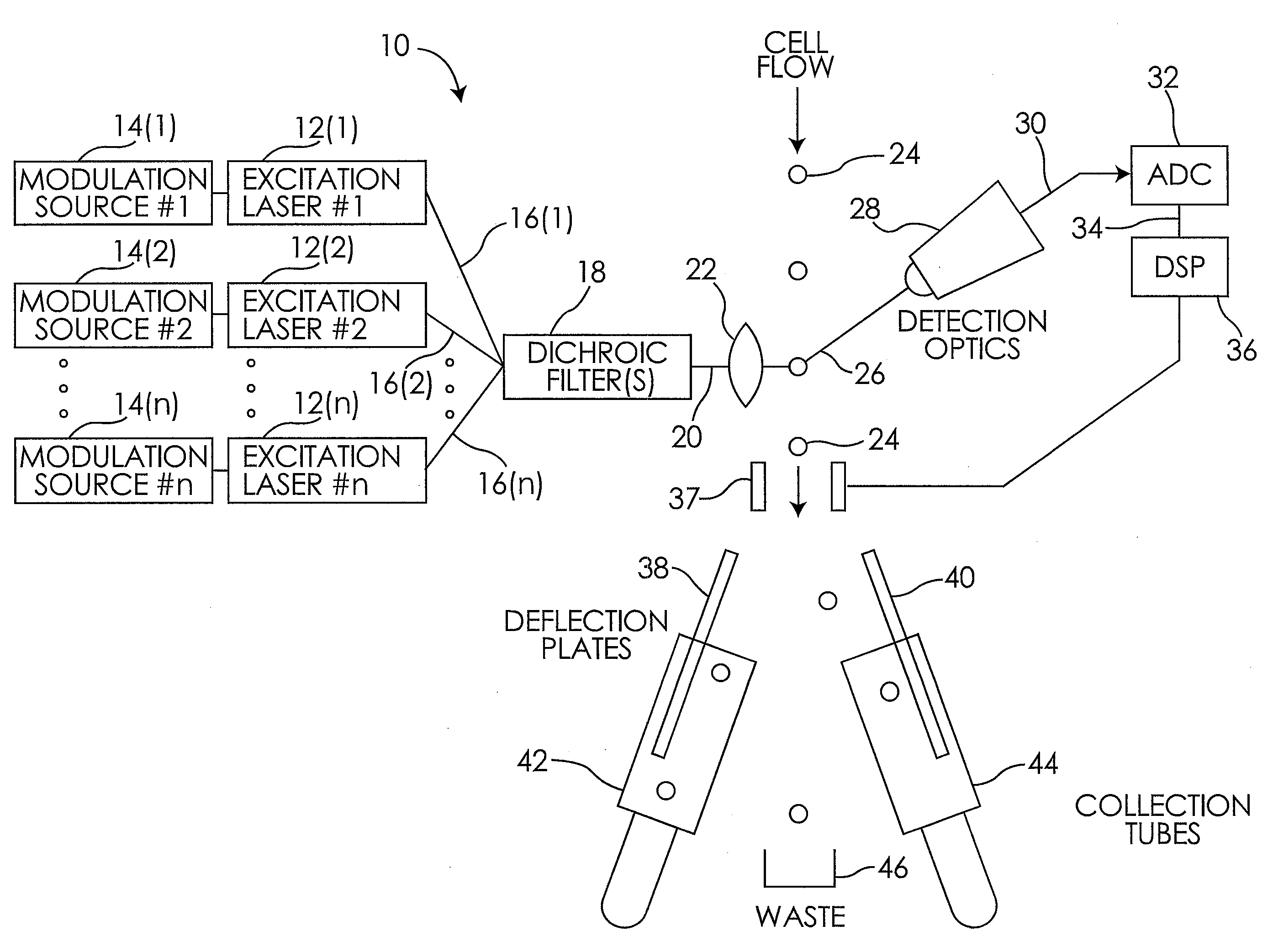
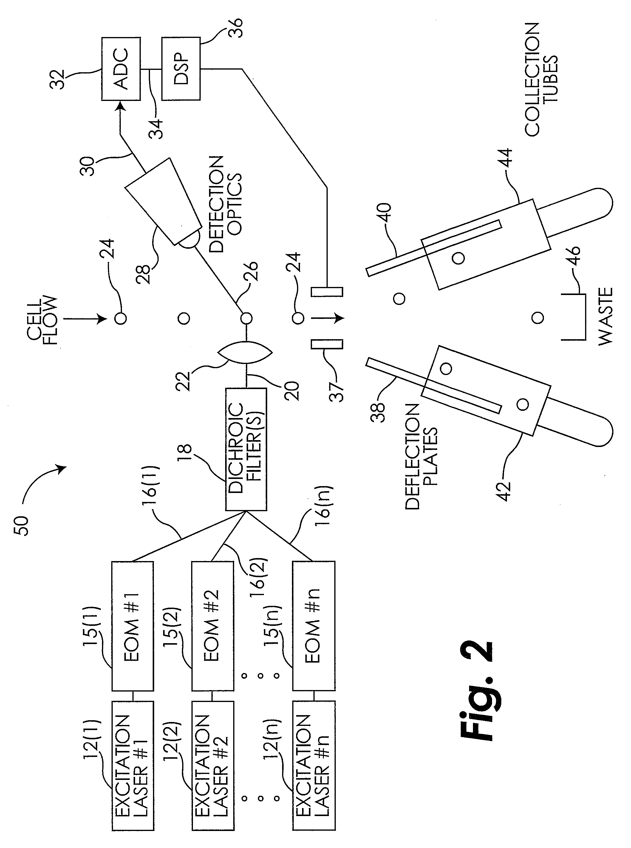
[0048]Electro-optic modulators (EOMs) (manufactured by Nova Phase, Inc., 43 Sparta Avenue, Newton, N.J. 07860) were used to modulate the continuous wave (CW) outputs of a LYT 200™ laser (λ=488 nm, power=100 mW, available from iCyt Visionary Bioscience, P.O. Box 1593, Champaign, Ill. 61824-1593) and an INNOVA® 90-C laser (λ=514 nm, power=100 mW, available from Coherent, Inc., 5100 Patrick Henry Drive, Santa Clara, Calif. 95054). The 488 nm laser was amplitude modulated using a sine function at 20 MHz and the 514 nm laser was amplitude modulated at 34 MHz. Ten micron diameter latex particles, labeled with a broad emission fluorescent dye that is stimulated into fluorescence at both 488 nm and 514 nm, were run through an iCyt Visionary Bioscience prototype cell sorter. Data were collected using custom software running on a Bittware TigerSharc DSP board equipped with a 105 MHZ Barracuda ADC (both available from Bittware Incorporated, 9 Hills Avenue, 2nd Floor, Concord, N.H. 03301). Data...


PUM

PropertyMeasurementUnit
Poweraaaaaaaaaa
Frequencyaaaaaaaaaa
Fluorescenceaaaaaaaaaa

Abstract

A system and method for the measurement of multiple fluorescence emissions in a flow cytometry system is disclosed where each excitation light source is modulated with a different frequency. A single detector is used to collect the fluorescent emissions excited by all light sources, and the emissions are segregated using Fourier Transform techniques. Systems and methods for the correction of inter-beam coincidence are also disclosed.

Description

CROSS-REFERENCE TO PRIOR APPLICATIONS[0001]The present application claims the benefit of U.S. Provisional Patent Application Ser. No. 60 / 892,716, filed Mar. 2, 2007 and entitled System and Method for the Measurement of Multiple Fluorescence Emissions in a Flow Cytometry System, the text and drawings of which are hereby incorporated by reference in their entireties.TECHNICAL FIELD OF THE INVENTION[0002]The Present invention generally relates to flow cytometry systems and, more particularly, to a system and method for the measurement of multiple fluorescence emissions in a flow cytometry system.BACKGROUND OF THE INVENTION[0003]Flow cytometry-based cell sorting was first introduced to the research community more than 20 years ago. It is a technology that has been widely applied in many areas of life science research, serving as a critical tool for those working in fields such as genetics, immunology, molecular biology and environmental science. Unlike bulk cell separation techniques su...

Claims


Application Information

Patent Timeline
IPC IPC(8): G01N21/64G01N21/00
CPCG01N15/1459
Inventor DURACK, GARYHATCHER, JEREMY
Owner SONY CORP
Why Eureka
Try Eureka