Cutting Tool Sharpener

a cutting tool and sharpener technology, applied in the field of tool sharpeners, can solve the problems of large burrs at the cutting edge, tendency to overheat the tool, dull cutting edge, etc., and achieve the effect of reducing the temperature of the tool

Active Publication Date: 2008-09-04
DAREX
View PDF24 Cites 11 Cited by
  • Summary
  • Abstract
  • Description
  • Claims
  • Application Information

AI Technical Summary

Benefits of technology

[0011]In accordance with other preferred embodiments, the apparatus generally comprises a rotatable abrasive surface, and a tool support structure which contactingly supports a body portion of a tool while a cutting surface of the tool is pre

Problems solved by technology

While such tools have found great popularity and utility in a variety of applications, one problem that often arises is that, after repeated use, the cutting edge can become dull and/or damaged.
While operable, a number of limitations have bee

Method used


Image

  • Cutting Tool Sharpener
  • Cutting Tool Sharpener
  • Cutting Tool Sharpener

Examples


Embodiment Construction

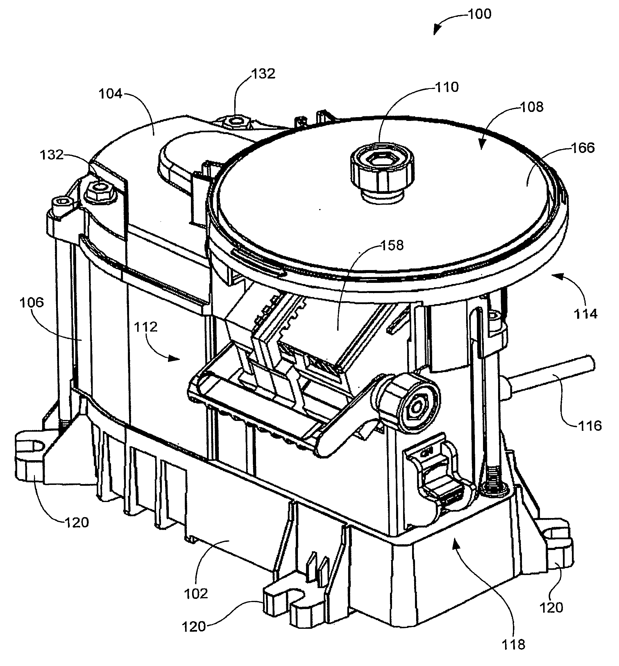
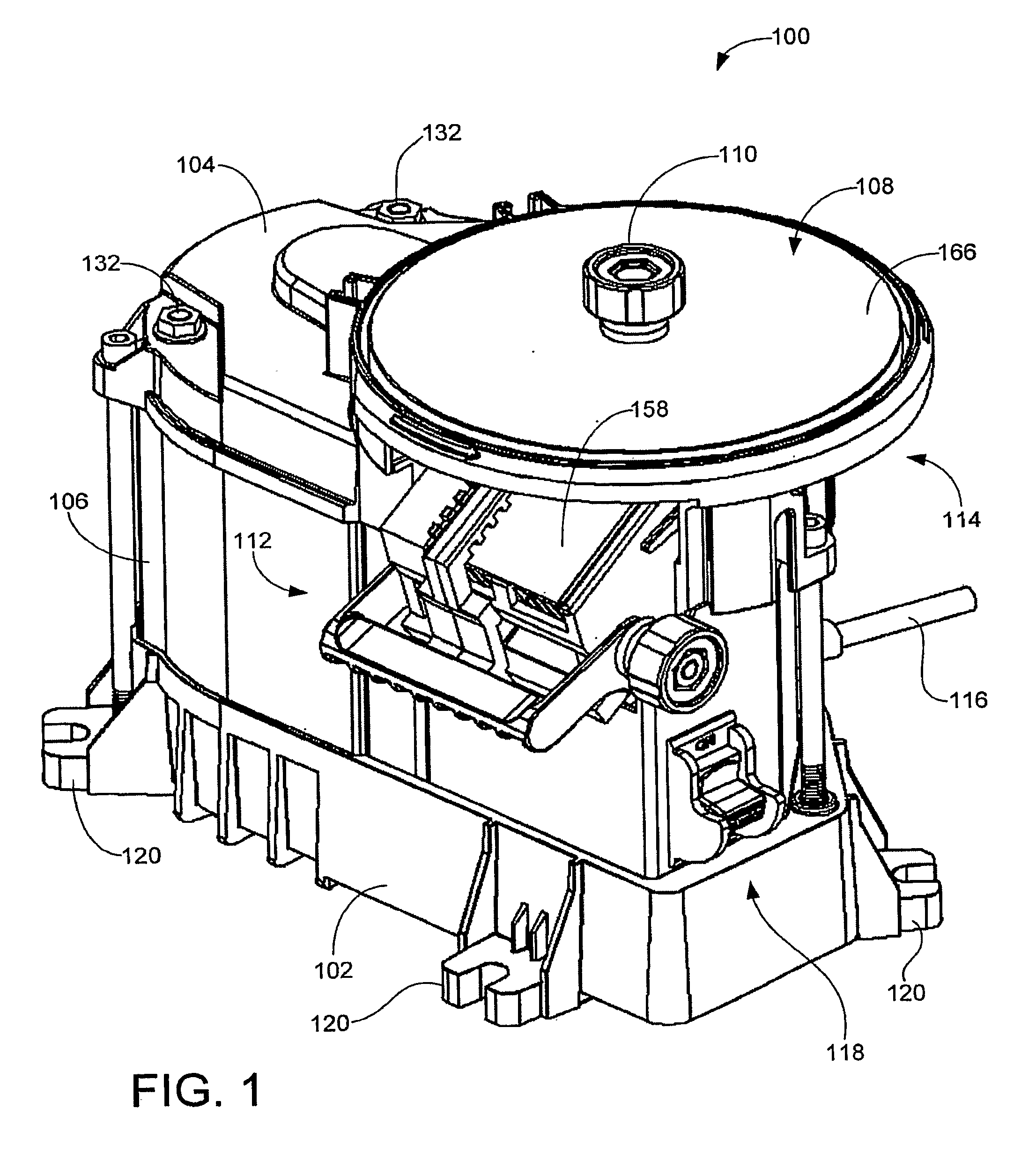
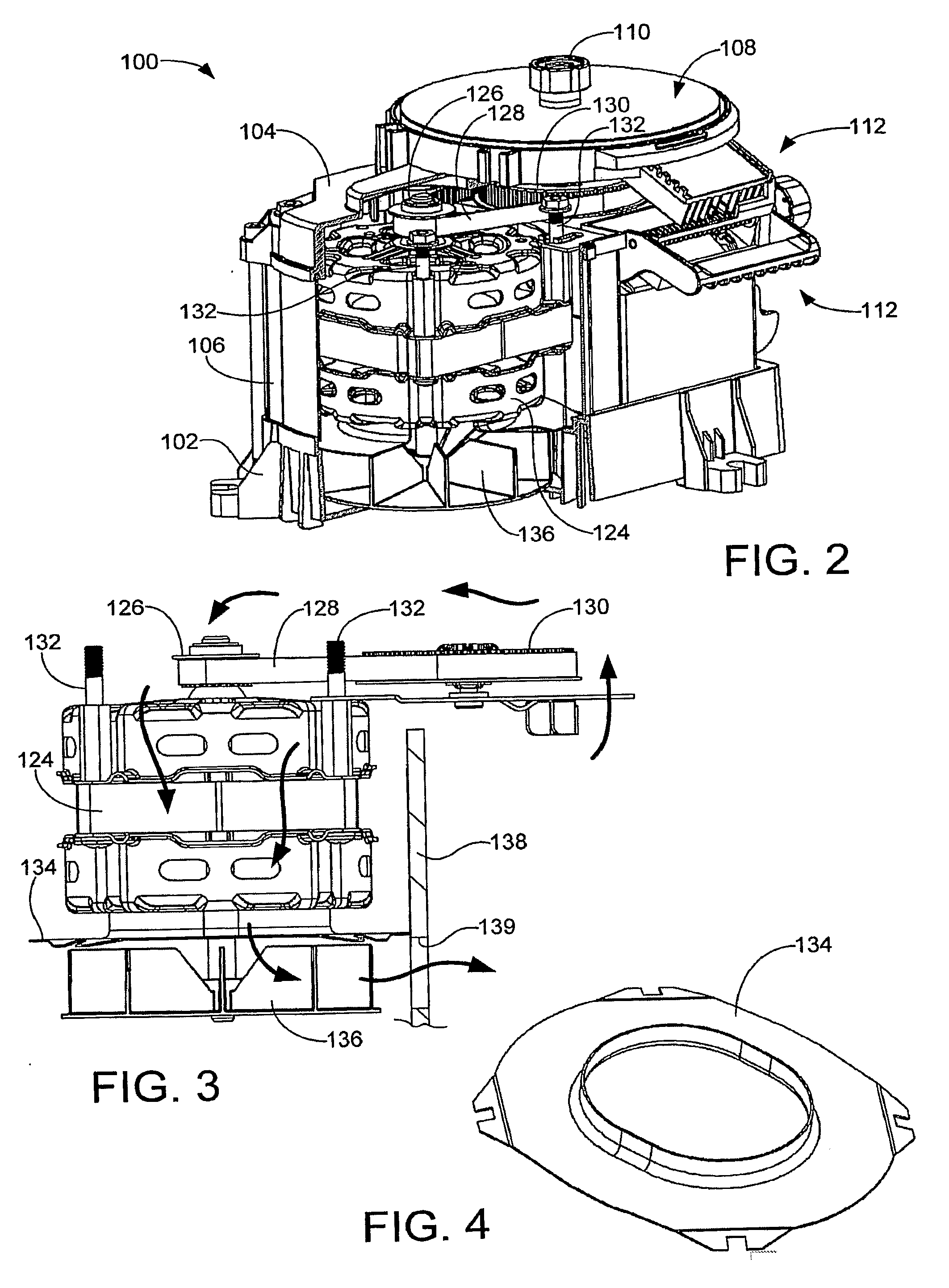
[0077]As set forth below, preferred embodiments of the present invention are generally directed to an apparatus for sharpening a cutting tool. The apparatus is exemplified by a tool sharpening assembly 100, as shown in FIG. 1. The assembly 100 includes a number of different features and operational assemblies, each of which will be discussed in turn below.

Overview

[0078]Major components of the assembly 100 include a rigid housing formed from a base member 102, top member 104 and circumferentially arrayed sidewall members 106. Preferably, the base member 102 is formed of injection molded, tool grade plastic, the top member 104 is cast aluminum and the sidewall members 106 are formed of aluminum sheeting. A variety of other materials and shapes can be used as desired, however.

[0079]An abrasive disc 108 is rotated during operation of the assembly 100 at a suitable speed, such as on the order of about 580 revolutions per minute (rpm). As explained below, the disc 108 preferably comprises...


PUM

PropertyMeasurementUnit
Temperatureaaaaaaaaaa
Lengthaaaaaaaaaa
Abrasiveaaaaaaaaaa

Abstract

A tool sharpening assembly (100) suitable for sharpening cutting tools (140,350,366,546,562). In some embodiments, a wedge-shaped port is formed between a rotational first abrasive surface (160,262) and a stationary second abrasive surface (162,264) to sharpen a distal cutting edge (146) of a cutting tool (140,230,546). In other embodiments, a cooling mechanism (136,326,330,334,338) actively draws heat generated during a sharpening operation from a tool (140) and through a tool support structure (170,234,328,332) contactingly supporting the tool, in further embodiments, a rotatable abrasive slotted disc (364) comprises at least one inspection aperture (372) formed from an interior sidewall (390) with upper and lower leading and trailing edges (396,398,400,402) of non-uniform separation distance. In other embodiments, a cylindrical drum abrasive member (572) is provided with an associated stationary support plate (574). In further embodiments, a grinding wheel (580,600) is formed of a substrate (582,602) and a plurality of abrasive layers (584,586,592,612,614) adhered thereto.

Description

FIELD OF THE INVENTION[0001]The claimed invention relates generally to the field of tool sharpeners and more particularly, but not by way of limitation, to an apparatus and method for sharpening a cutting tool.BACKGROUND[0002]Cutting tools are often provided with a laterally extending cutting (chisel-type) edge. This cutting edge is useful, for example, in planing a surface such as a wooden board, or cutting a brick or other member through the application of a sharp impulse to the tool opposite the cutting edge.[0003]The cutting edge is often defined at the intersection of a back surface and leading surface (bevel) of the tool. The angle between the respective back and bevel surfaces can vary, with a commonly used angle being on the order of about 25 degrees.[0004]The laterally extending cutting edge can be substantially linear (straight), or can be curvilinear (rounded). These latter tools are particularly useful as woodworking and carving tools, which come in a large number of sha...

Claims


Application Information

Patent Timeline
IPC IPC(8): B24B3/00B24B9/00
CPCB24B3/36B24B3/34B24B3/54B24B9/04B24B55/02
Inventor DOVEL, DANIEL T.DELORENZO, CHRISTOPHER T.MINER, STEVEN J.
Owner DAREX
Why Eureka
Try Eureka