Drilling apparatus and system for drilling wells

a drilling apparatus and well technology, applied in the direction of drilling pipes, directional drilling, borehole/well accessories, etc., can solve the problems of reducing the efficiency of drilling operation, and generating the torque of the bit, so as to reduce the cost of rig time and reduce the damage to the skin , the effect of saving cos

Inactive Publication Date: 2008-09-11
SOUTHARD DRILLING TECH
View PDF0 Cites 7 Cited by
  • Summary
  • Abstract
  • Description
  • Claims
  • Application Information

AI Technical Summary

Benefits of technology

[0021]An advantage of the present invention is the ability to drill with non-reactive torque utilizing a first bit and a second concentric bit. An advantage of the present system is that wells can be drilled and completed faster. Another advantage is that the work string used with the dual bit is a casing string. Yet another advantage is that the casing string can be left in the hole after the intended total depth of the well is reached.
[0022]Still yet another advantage is that after drilling the well, the well can be cemented. By cementing the well quicker than prior art methods, the well will experience less skin damage to potential hydrocarbon bearing reservoirs. Another advantage is that operators will realize significant cost savings due to significantly faster completion times. Another feature is that the drilling apparatus can utilize coiled tubing string as a work string, and wherein drilling is possible utilizing the coiled tubing string due to the non-reactive torque produced by the disclosed drilling apparatus.
[0023]An advantage of the most preferred embodiment is to maximize the removal of drill cutting by directing drilling fluid flow from the mud supply in the drill string directly to the outer bit. Another advantage of the most preferred embodiment is the placement and direction of the flow nozzles. The upward direction of the nozzles will provide a Venturi effect that will reduce the bottom-hole pressure below the nozzles. The resulting reduction of bottom-hole pressure will improve both the hydraulic and drilling performance of the inner bit.
[0024]A feature of the present invention includes the ability to drill-in with the casing string without the need to pull the entire length of casing string from the well. Yet another feature is that the casing string can be cemented into the well. Yet another feature is the option to perforate the casing string to produce hydrocarbon reservoir. Another feature is that the drill-in casing string can employ the same thread connection means used on commercially available casing strings. In other words, commercially available thread means can be used with the drill-in casing. Yet another feature is the pinions are mounted about pins, and wherein the pins are mounted on a radial shoulder of the sleeve, and therefore, the pinions are capable of rotation. Still yet another feature is that the down hole motors used with the disclosed system are commercially available.
[0025]A feature of the most preferred embodiment is the placement of the nozzles, which may be in a cross-over sub, between the drive shaft and the inner bit. Another feature may be to add a flow directing skirt to the cross-over sub which will direct drilling fluid flow toward the outer bit and the junk slot area and out into the annulus. The combination of the nozzles and the skirt will help lift the cuttings generated by the inner bit and very efficiently clean the outer bit as it drills. The nozzles will be facing upward at optimal angles and be directed at the point of interaction between the outer bit and the rock. This direction will jet the cuttings away from the outer bit immediately after being cut and keep the outer bit clean to avoid cuttings build-up and keep the annulus moving to efficiently transport cuttings up and out of the hole. Yet another feature of the most preferred embodiment is that the nozzles will include about three separate nozzles angled upwards at an approximate 45 degree angle, aimed at the cutters of the outer bit.

Problems solved by technology

A common problem with this type of drilling assembly is the torque generated by the bit.
These numerous adjustments cost valuable rig time and reduce the efficiency of the drilling operation.
As those of ordinary skill in the art will appreciate, daily rig cost are substantial.
Prior art tools have not allowed an operator to effectively drill with a casing string forming a part of the work string due to structural limitations of the casing string and the casing string thread connections.
In other words, the casing strings and casing string connections are not structurally designed to handle the stress and strain applied by the numerous torquing requirements for a drill string.

Method used


Image

  • Drilling apparatus and system for drilling wells
  • Drilling apparatus and system for drilling wells
  • Drilling apparatus and system for drilling wells

Examples


Embodiment Construction

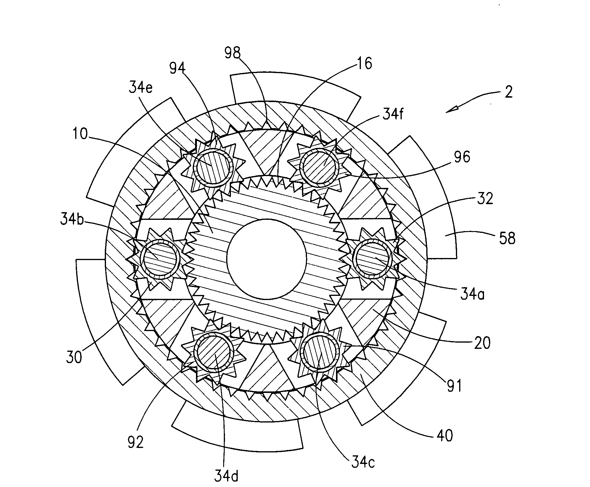
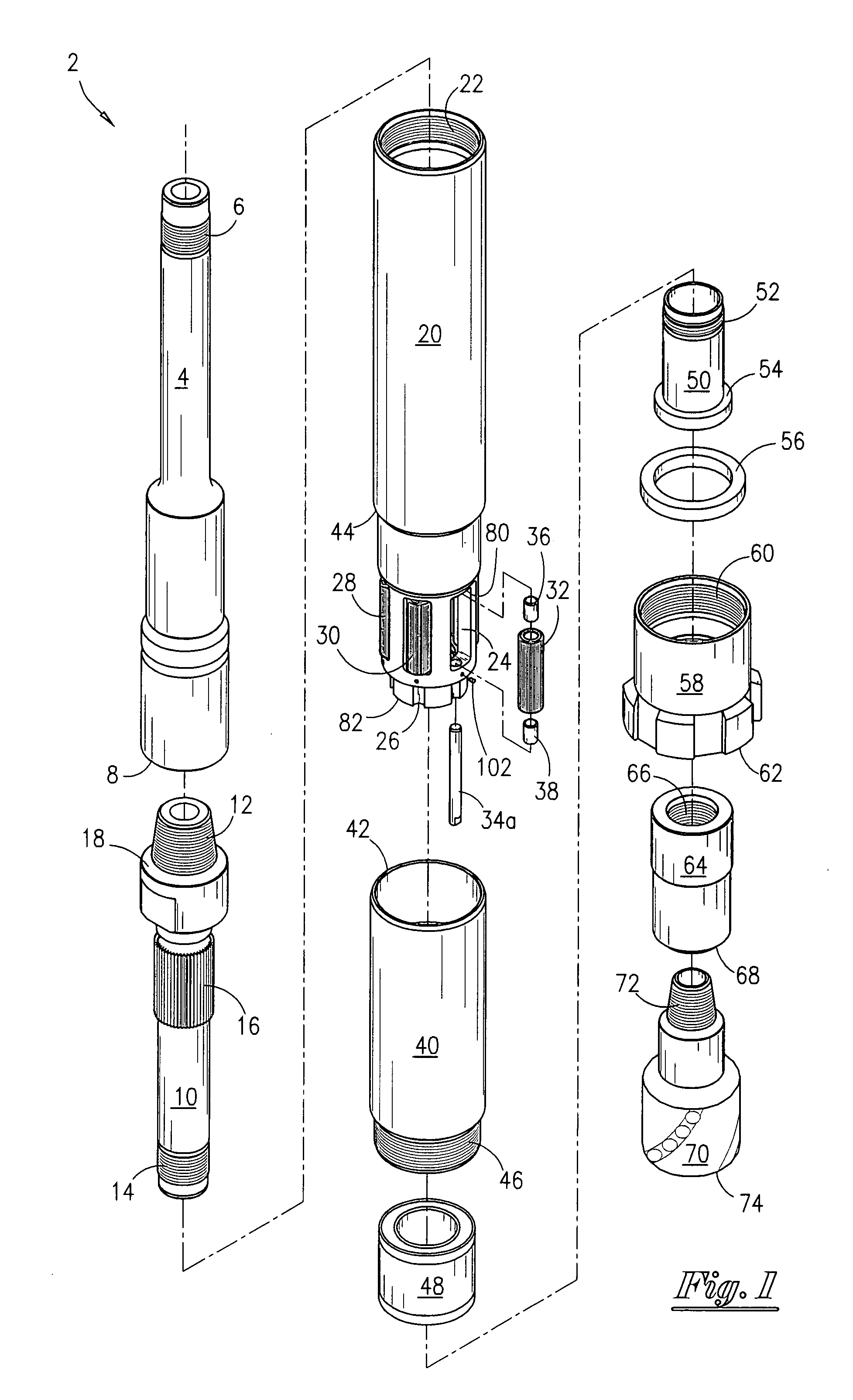
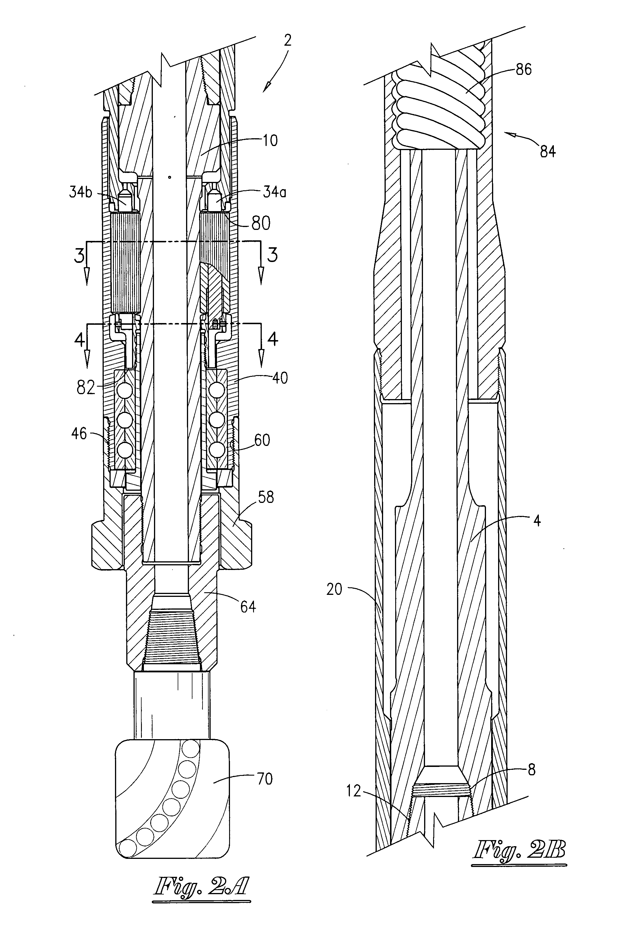
[0037]Referring now to FIG. 1, a perspective view of the drilling apparatus 2 of the present disclosure will now be described. The power shaft 4 has a first end with external threads 6 and a second end with internal threads 8. A driver 10 will threadedly connect with the power shaft 4. The driver 10 has a first end having external threads 12 that will engage with the internal threads 8 and a second end having external threads 14. As seen in FIG. 1, driver 10 has a cylindrical body having a plurality of cogs 16 (sometimes referred to as splines 16) as well as the raised shoulder 18. A sleeve 20 is included, and wherein the sleeve 20 has internal thread means 22 on one end and a second end having a plurality of openings, such as seen at 24. Also, on the radial end, a plurality of indentations have been formed, such as seen at 26.

[0038]FIG. 1 also depicts the pinions 28, 30, 32, and wherein the pins will be disposed there through for rotation. Hence, the pin 34a will be disposed throug...


PUM


Abstract

A device for boring a well. The device is attached to a motor that has a power shaft for imparting rotational movement. The device comprises a driver operatively connected to the power shaft, with the driver containing a tubular body, a first bit having a first end connected to the driver so that rotational movement of the driver is imparted to the first bit, and a sleeve disposed about the power shaft, and wherein the sleeve has a radial shoulder. The device further comprises a housing disposed about the driver and a second bit attached to the housing. A plurality of nozzles is operatively placed within the driver, and the nozzles deliver fluid flow to the second bit. The device may further include a planetary gear anchored to the radial shoulder, and wherein the planetary gear is adapted for imparting rotation from the driver to the housing in a counter radial direction.

Description

BACKGROUND OF THE INVENTION[0001]This application is a continuation-in-part application of my co-pending application bearing Ser. No. 11 / 713,942, filed 5 Mar. 2007, and entitled “Drilling Apparatus and System for Drilling Wells”. This invention relates to a novel drilling device and method of drilling a well. More particularly, but not by way of limitation, this invention relates to a non-reactive torque device that contains an inner bit and a counter-rotating outer bit. This invention also describes a method of drilling the well while utilizing nozzles that aid in the drilling process.[0002]In the search for oil and gas, operators have utilized various types of devices in order to drill wells. Operators are continually searching for ways to drill the wells faster and more economically. Traditionally, a specifically designed drill string was used to drill wells. The drill string would have attached thereto a drill bit. In order to drill the well, the driller would cause the drill st...

Claims


Application Information

Patent Timeline
Patent Type & Authority Applications(United States)
IPC IPC(8): E21B3/00E21B17/00E21B7/04
CPCE21B4/006E21B7/068E21B4/02
Inventor SOUTHARD, ROBERT CHARLES
Owner SOUTHARD DRILLING TECH
Why Eureka
Try Eureka