Control Device for Motor Drive System and Electric Vehicle Including the Same

Active Publication Date: 2008-09-11
DENSO CORP
View PDF12 Cites 54 Cited by
  • Summary
  • Abstract
  • Description
  • Claims
  • Application Information

AI Technical Summary

Benefits of technology

[0022]According to the control device for the motor drive system as described above, at a time of motor rotational speed sudden decrease when the motor current is disturbed in t

Problems solved by technology

However, in the sinusoidal PWM control method, a fundamental component of an output voltage of the inverter cannot be increased enough and voltage utilization is limited, so that it is difficult to obtain a high power in a high rotational speed region.
In addition, a distortion component of motor current is greater because of a greater distortion in the motor applied voltage waveform.
Furthermore, even in the overmodulation control method, a distortion component of motor current is greater similarly, and the controllability is degraded by the aforementioned filter processing, as compared with the s

Method used


Image

  • Control Device for Motor Drive System and Electric Vehicle Including the Same
  • Control Device for Motor Drive System and Electric Vehicle Including the Same
  • Control Device for Motor Drive System and Electric Vehicle Including the Same

Examples


Example

First Embodiment

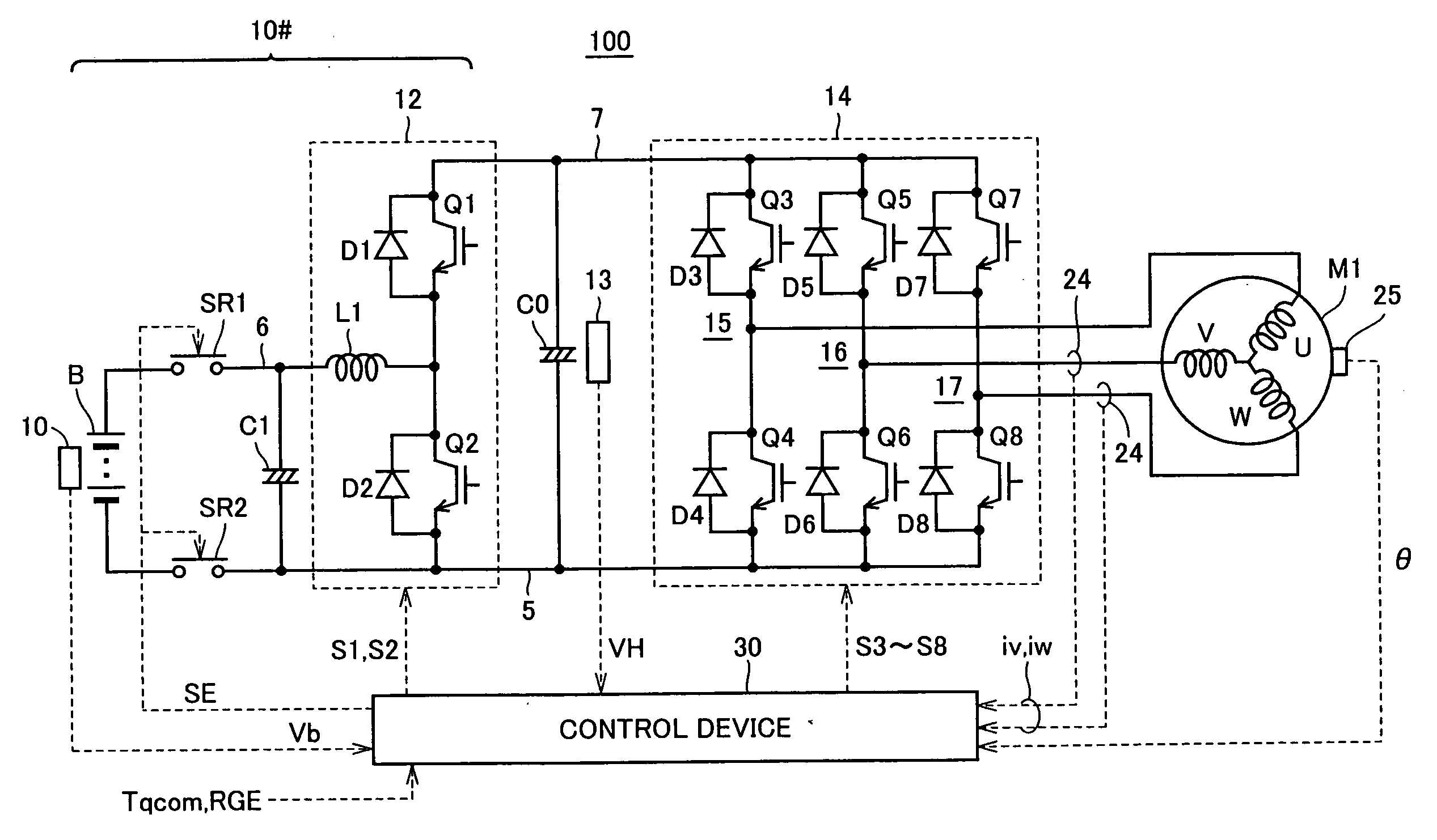
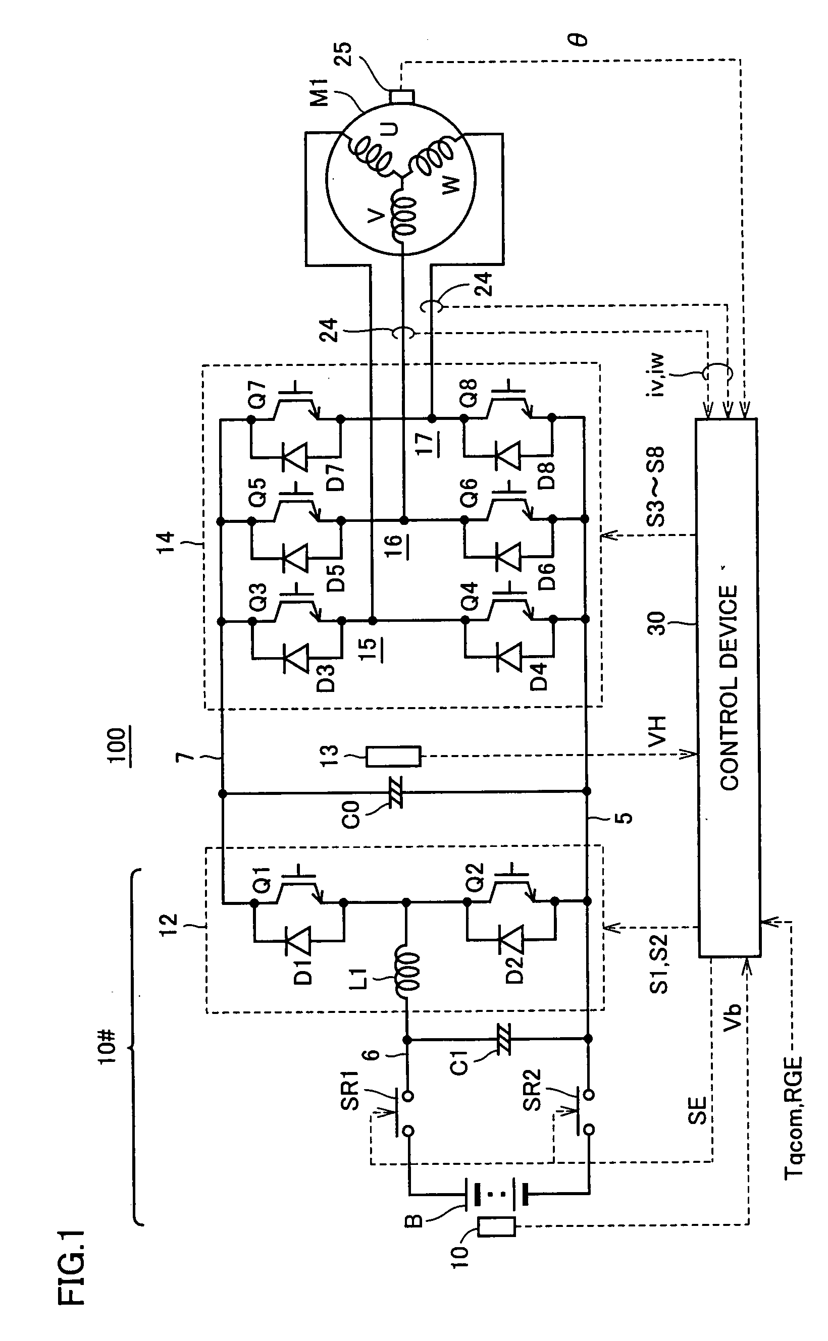
[0044]FIG. 1 is an entire configuration diagram of a motor drive system in accordance with an embodiment of the present invention.

[0045]Referring to FIG. 1, a motor drive system 100 in accordance with an embodiment of the present invention includes a DC voltage generation portion 10#, a smoothing capacitor C0, an inverter 14, and an AC motor M1.

[0046]AC motor M1 is, for example, a driving electric motor generating torque for driving drive wheels mounted on an electric vehicle such as a hybrid car or an electric car. Alternatively, this AC motor M1 may be configured to have a function of a power generator driven by an engine and may be configured to have both functions of an electric motor and a power generator. Furthermore, AC motor M1 may be built in a hybrid car as operating as an electric motor for an engine and being capable of engine start-up, for example.

[0047]DC voltage generation portion 10# includes a DC power supply B, system relays SR1, SR2, a smoothing ca...

Example

Second Embodiment

[0129]In a second embodiment, a variation of the control configuration for solving the similar technical problem at a time of rectangular wave control method will be described. It is noted that the control configuration in accordance with the second embodiment corresponds to the time of a decrease of the motor revolutions when the motor current is disturbed in the excessively increasing direction.

[0130]FIG. 13 is a control block diagram of the rectangular wave control by the control device for the motor drive system in accordance with the second embodiment.

[0131]In FIG. 13, in comparison with FIG. 6, in the rectangular wave control configuration in accordance with the second embodiment, a rectangular wave duty control portion 330 is additionally provided to the control configuration shown in FIG. 6. The configuration in the other parts is similar to that of FIG. 6 and therefore the detailed description will not be repeated.

[0132]Rectangular wave duty control portion...

Example

Third Embodiment

[0143]In a third embodiment, a variation of the control configuration for solving the similar technical problem at a time of overmodulation PWM control method will be described.

[0144]FIG. 18 is a control block diagram of PWM control by the control device for the motor drive system in accordance with the third embodiment.

[0145]In FIG. 18, in comparison with FIG. 5, in the control configuration in accordance with the third embodiment, a voltage command correction portion 245 used at a time of overmodulation control mode is additionally provided in PWM control block 200. The configuration in the other parts is similar to that of FIG. 5 and therefore the detailed description will not be repeated.

[0146]FIG. 19 is a flowchart illustrating the operation of voltage command correction portion 245.

[0147]Referring to FIG. 19, in step S300, voltage command correction portion 245 determines whether overmodulation control is in progress or not, based on the output of control mode ...


PUM


Abstract

A square wave voltage having an amplitude equal to an output voltage of a converter is applied to an AC motor by a square wave control block. Torque control of the AC motor is performed basically by changing the voltage phase of the square wave voltage according to the torque deviation. When the motor revolution is suddenly changed, a instruction value correction unit sets a voltage instruction value of the output voltage of the converter according to a change ratio of the motor revolutions. This improves control of the motor current by changing the voltage applied to the motor in accordance with the sudden change of the motor revolutions without waiting for torque feedback control having a low control response.

Description

TECHNICAL FIELD[0001]The present invention relates to a control device for a motor drive system and an electric vehicle including the same, and more particularly to a control device for a motor drive system converting DC voltage into AC voltage by an inverter to be applied to an AC motor.BACKGROUND ART[0002]A motor drive system is generally used which converts DC voltage into AC voltage by an inverter to drive and control an AC motor. In such a motor drive system, generally, motor current is controlled according to sinusoidal PWM (Pulse Width Modulation) control based on vector control for driving an AC motor with high efficiency.[0003]However, in the sinusoidal PWM control method, a fundamental component of an output voltage of the inverter cannot be increased enough and voltage utilization is limited, so that it is difficult to obtain a high power in a high rotational speed region. In consideration of this point, employment of a modulation method that allows outputting a voltage w...

Claims


Application Information

Patent Timeline
IPC IPC(8): H02P27/08H02P23/14H02P21/00H02P21/22H02P23/07H02P27/06
CPCH02P6/142H02P21/06H02P21/0089H02P6/15
Inventor OKAMURA, MASAKI
Owner DENSO CORP
Why Eureka
Try Eureka