Optical pickup, optical information recording and reproducing apparatus and method for optically recording and reproducing information

a technology of optical information and optical pickup, which is applied in the field of optical pickup, optical information recording and reproducing apparatus and method for optically recording and reproducing information, can solve the problems of large number of optical components, degraded quality of the signal to be recorded, and method not suited to compact optical systems. achieve the effect of high reliability

Inactive Publication Date: 2008-09-11
AKONIA HOLOGRAPHICS +1
View PDF6 Cites 7 Cited by
  • Summary
  • Abstract
  • Description
  • Claims
  • Application Information

AI Technical Summary

Benefits of technology

[0014]The present invention is made in consideration of the above-described problem, and an object of the present invention is to provide an optical pickup which (1) is compact and (2) has a high reliability, an optical information recording / reproducing method and an optical information recording / reproducing apparatus.
[0016]The present invention adopts a structure that the reference beam becomes incident upon the same lens as the lens (first lens) for converging the signal beam upon the optical information recording medium. It is necessary, however, as described above, that the reference beam is applied to the medium in the parallel beam state. To this end, in the present invention, a second lens for conversing the reference beam upon the front focus plane of the converging lens is disposed on the optical path of the second beam, so that the reference beam can be applied to the medium in the parallel beam state. It is therefore possible for the signal beam and reference beam to share the optical path from the first lens to the optical information recording medium.
[0018]By using the optical pickup constructed as above, it becomes possible to achieve the above-described object (1) to realize a compact optical pickup.
[0019]Furthermore, the optical pickup of the present invention has means for correcting various influences to be caused by a variation in beam application conditions of an optical system. Factors of the variation in beam application conditions include, for example, an inclination of an optical information recording medium to be used in combination with the optical pickup adopting the present invention, a shift amount of a wavelength of an optical beam applied from a light source, and the like. It is therefore possible to achieve the above-described object (2) to realize a high reliability optical pick up.
[0021]According to the present invention, since the signal beam and reference beam propagate along substantially the same optical path, it is advantageous in that an optical system can be made more compact than using a conventional angle multiplexing method. In addition, a recording quality of a signal can be improved drastically, because it is possible to mitigate a shift of the wavefront and optical path length of the signal beam and reference beam to be caused by vibrations, a fluctuation of atmospheric air and positional displacement of optical components during propagation. Further, degradation of a reproduction signal caused by inclination of the optical information recording medium can be corrected by driving a lens in a direction perpendicular to an optical axis. Furthermore, color aberration can be corrected by driving a lens in an optical axis direction.

Problems solved by technology

Therefore, the number of optical components is large and this method is not suited for compacting an optical system more than a conventional optical pickup such as BD.
However, there occurs a shift of the wavefront and optical path of the signal beam and reference beam due to vibration and fluctuation of atmospheric air, and the quality of a signal to be recorded is degraded, posing a problem of difficulty in practical use.

Method used


Image

  • Optical pickup, optical information recording and reproducing apparatus and method for optically recording and reproducing information
  • Optical pickup, optical information recording and reproducing apparatus and method for optically recording and reproducing information
  • Optical pickup, optical information recording and reproducing apparatus and method for optically recording and reproducing information

Examples


first embodiment

[Overall Structure of Holographic Information Recording / Reproducing Apparatus]

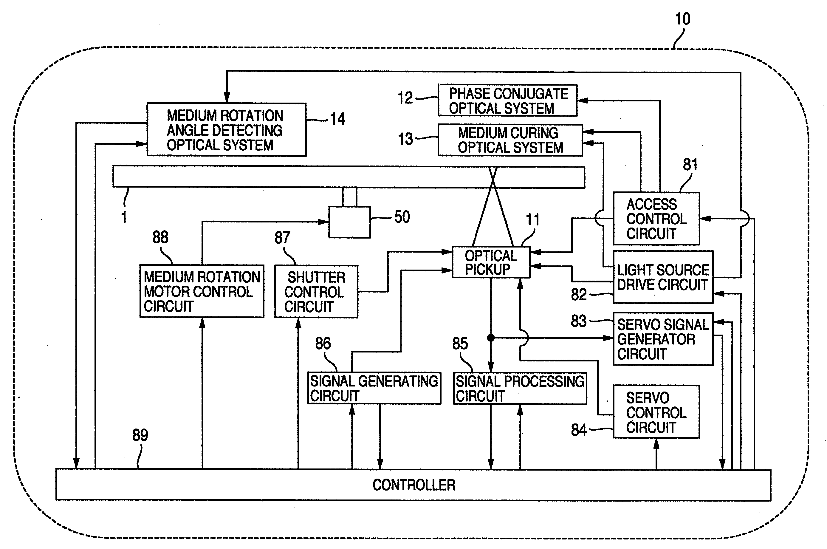
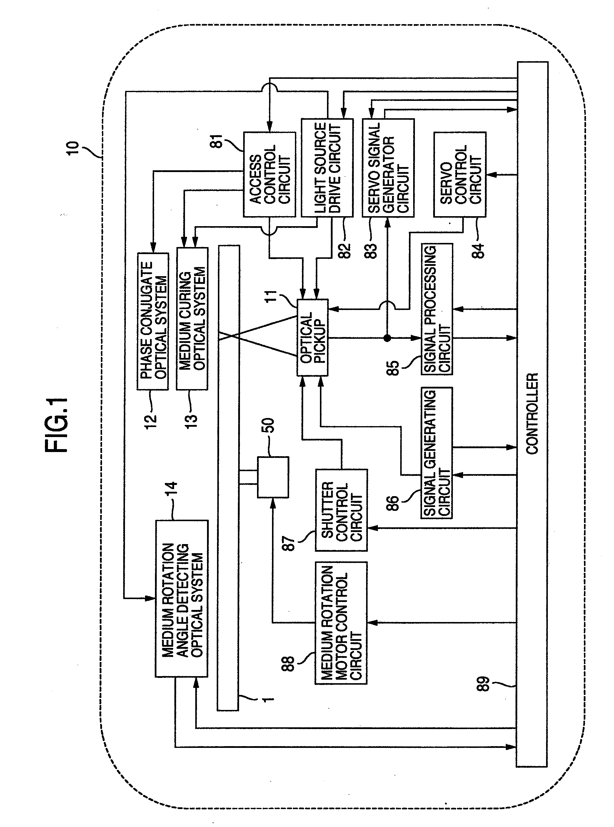
[0033]FIG. 1 shows the overall structure of a holographic information recording / reproducing apparatus for recording and / or reproducing digital information by utilizing holography.

[0034]A holographic information recording / reproducing apparatus 10 is constituted of an optical pickup 11, a phase conjugate optical system 12, a medium curing optical system 13, a medium rotation angle detecting optical system 14 and a rotation motor (spindle motor) 50. The optical information recording medium 1 is structured being able to be rotated by the rotation motor 50.

[0035]The optical pickup 11 has a role of recording digital information by applying a reference beam and a signal beam to the optical information recording medium 1 by utilizing holography.

[0036]In operation, a controller 89 operates to send an information signal to be recorded to a spatial light modulator in the optical pickup 11 to be described later via a ...

second embodiment

[0058]FIGS. 4A and 4B show another example of the optical system structure of the optical pickup 11 of the Monocular system shown in FIGS. 3A and 3B. FIG. 4A shows a recording state. An optical beam emitted from a light source 301 transmits through a collimator lens 302 and becomes incident upon a shutter 303. The shutter 303 has an aperture or opening through which light passes, and an optical transmission quantity can be adjusted by inserting and retracting a light shielding plate. While the shutter 303 is open, the optical beam passes through the shutter 303, and thereafter becomes incident upon a signal beam shutter 401. The optical beam incident upon the shutter 401 is subjected to area division such that a portion of the beam is for a reference beam 312 and another portion is for a signal beam 306.

[0059]The signal beam (P polarized beam) 306 passed through the polarization beam splitter 307 becomes incident upon a spatial light modulator 308 added with a quarter wave plate, vi...

third embodiment

[0069]FIGS. 5A and 5B show another example of the optical system structure of the optical pickup 11 of the Monocular system shown in FIGS. 3A and 3B. Description will be omitted on the same function as that of the optical system of the optical pickup 11 of the Monocular system shown in FIGS. 4A and 4B. FIG. 5A shows a recording state. An optical beam is separated by an optical component 501 into a parallel beam as the signal beam 306 and a converged beam as the reference beam 312 indicated by a broken line. For example, the optical component 501 is a diffraction lens 601 shown in FIG. 6 and uses a 0-th order beam as the signal beam and a 1-st order diffraction beam as the reference beam. In this structure, the 0-th order beam may be used as the reference beam and the 1-st order diffraction beam as the signal beam. By using the 0-th order beam and 1-st order diffraction beam either as the signal beam or as the reference beam in the above manner, an optical pickup can be realized whic...


PUM

PropertyMeasurementUnit
wavelength orderaaaaaaaaaa
opticalaaaaaaaaaa
areaaaaaaaaaaa

Abstract

An optical pickup for recording a hologram by using an angle multiplexing method. An optical beam is separated into two beams, a signal beam and a reference beam having different convergence / divergence degrees, by using an optical component such as a diffraction lens. The signal and reference beams are made incident upon the same objective, and the optical component or the objective lens is moved in a direction perpendicular to an optical axis, to thereby realize angle multiplex recording. If an optical information recording medium is inclined, the optical component or the objective lens is moved along the direction along which the optical information recording medium moved to change an angle of the reference beam incident upon the optical information recording medium and compensate for degradation of a reproduction signal.

Description

INCORPORATION BY REFERENCE[0001]The present application claims priority from U.S. Provisional Patent Application Ser. No. 60 / 905,837 filed on Mar. 9, 2007, the content of which is hereby incorporated by reference into this application.CROSS-REFERENCE TO RELATED APPLICATION[0002]The present application relates to subject matter described in application Ser. No. 12 / 038,150 filed on Feb. 27, 2008, entitled “OPTICAL PICKUP, OPTICAL INFORMATION RECORDING APPARATUS AND OPTICAL INFORMATION recording and REPRODUCING APPARATUS USING THE OPTICAL PICKUP” by Kenichi SHIMADA, Tatsuro IDE, Kevin R. CURTIS and Ken E. ANDERSON, claiming priority from U.S. provisional application Ser. No. 60 / 905,838, filed on Mar. 9, 2007. The entire content of the related application is incorporated herein by reference.BACKGROUND OF THE INVENTION[0003]The present invention relates to an apparatus and holographic recording / reproducing method for recording information in an optical information recording medium and / or...

Claims


Application Information

Patent Timeline
Patent Type & Authority Applications(United States)
IPC IPC(8): G11B7/00G11B7/135
CPCG11B7/00772G11B7/1378G11B7/1353G03H1/041
Inventor IDE, TATSUROSHIMADA, KENICHITAKAHASHI, MASAHIKOSHIMANO, TAKESHICURTIS, KEVIN R.ANDERSON, KEN E.
Owner AKONIA HOLOGRAPHICS
Why Eureka
Try Eureka