Carbonizing Apparatus

a technology of carbonizing apparatus and cylinder, which is applied in the direction of stationary retorts, biofuels, energy inputs, etc., can solve the problems of difficult temperature control of material under treatment b>1/b>′ in the rotary kiln b>270/b>, time and effort in maintenance for securing passage in the duct, and achieves the effect of easy burning of distillation gas slowly

Inactive Publication Date: 2008-09-18
SUNTORY HLDG LTD
View PDF3 Cites 0 Cited by
  • Summary
  • Abstract
  • Description
  • Claims
  • Application Information

AI Technical Summary

Benefits of technology

[0031]With this characteristic construction, the exhaust heat of the exhaust gas can be used effectively within a system of the carbonizing apparatus. Particularly since the exhaust gas having passed the exhaust heat recovery boiler is supplied to the premix combustion section, it is easy to burn the distillation gas slowly and at low combustion temperature by mixing the exhaust gas at low temperature into the distillation gas.

Problems solved by technology

In this case, a substance produced from the distillation gas condensed within the duct 274 tends to collect in the duct 274, which gives rise to a problem that it takes time and effort in maintenance for securing passage in the duct 274.
Hence, this system has a disadvantage that supplying of the air for spontaneous combustion is difficult.
As a result, there is also a problem that temperature control of the material under treatment 1′ in the rotary kiln 270 is difficult.

Method used


Image

  • Carbonizing Apparatus
  • Carbonizing Apparatus
  • Carbonizing Apparatus

Examples


first embodiment

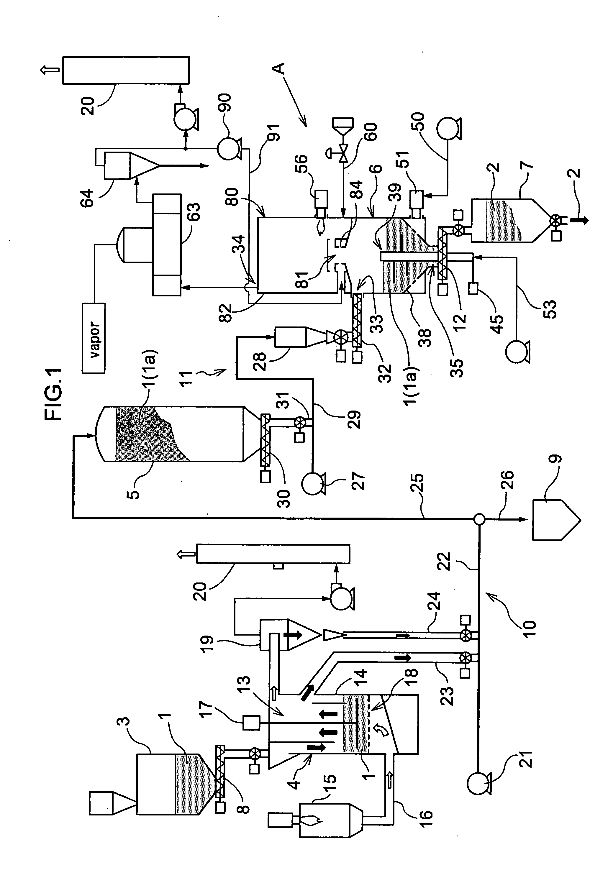
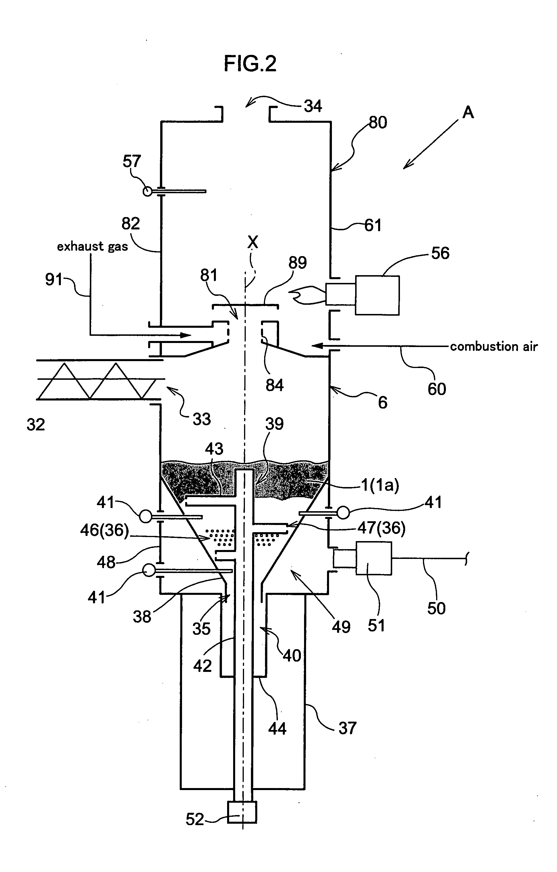
[0033]FIG. 1 shows a carbonizing system for carbonizing residues produced in a coffee extraction process, i.e. coffee grounds. This carbonizing system includes, mainly, a receiving hopper 3 into which coffee grounds are introduced as material under treatment 1, a drier 4 for drying the material under treatment 1, a dried material storage tank 5 for storing the dried material under treatment 1 (1a), a carbonizing apparatus A according to this invention for carrying out carbonizing treatment of the dry material under treatment 1a, and a carbide storage tank 7 for storing carbide 2 obtained. This carbonizing system further includes a screw feeder 8 for transporting the material under treatment 1 in the receiving hopper 3 to the drier 4, a dry material transporting device 10 for transporting the dry material under treatment 1a dried in the drier 4 to the dry material storage tank 5 or a hopper 9 for delivery to the outside, a dry material feeding device 11 for feeding the dry material u...

second embodiment

[0055]FIG. 5 shows a different embodiment of a carbonizing system according to this invention. In this carbonizing system, a cylindrical drier 104 is disposed on top of and coaxially and integrally with a carbonizing apparatus A. As a drying gas supply path 166 for supplying the drier 104 with exhaust gas generating in a combustion furnace 180 of the carbonizing apparatus A as drying gas, a duct 165 connecting an exhaust outlet 134 of the combustion furnace 180 and a drying chamber 113 of the drier 104 extends outside the combustion furnace 180. Further, a drying gas blowoff device 118 is provided that can form a fluid bed by blowing off the drying gas to material under treatment 1 in the drying chamber 113 from below. Thus, the material under treatment 1 can be dried while being agitated in a floating state.

[0056]The drying gas having passed through the drying chamber 113 is stripped of fine particles of the material under treatment and the like in a cyclone separator 119. The dryi...


PUM

PropertyMeasurementUnit
gravityaaaaaaaaaa
speedaaaaaaaaaa
temperatureaaaaaaaaaa

Abstract

This invention provides a carbonizing apparatus for easily carbonizing a material to a desired state of carbonization, which apparatus requires a reduced installation space, and lowers concentration of harmful gases contained in an exhaust gas. The interior of a cylindrical furnace body 82 having a vertical axis is divided by a partition wall 83 into an upper furnace body acting as a combustion section 80 and a lower furnace body acting as a carbonization section 6. The partition wall 83 defines a through hole for supplying distillation gas to the combustion section 80. The carbonization section 6 has a vertical structure, with a supply part 33 disposed in an upper portion for supplying a material under treatment 1, and a carbide take-out part 35 and a first blowoff part 36 of spontaneous combustion air disposed in a lower portion, so that the material under treatment 1 is movable by gravity toward the take-out part 35. An agitating device 39 includes agitating members 43 revolvable about a vertical axis. A premix combustion section 81 is provided on the combustion part 80 side of the partition wall 83 for mixing a distillation gas having passed through the through-hole with an exhaust gas discharged from a discharge part 34 and burning the mixture. Gas having passed through the premix combustion section 81 is supplied to the combustion section 80.

Description

TECHNICAL FIELD[0001]This invention relates to a carbonizing apparatus comprising a carbonization section including a supply part for supplying a material under treatment, an agitating device for agitating the material under treatment supplied from the supply part, a first blowoff part for blowing off spontaneous combustion air for the material under treatment, adjusting means for adjusting quantity of the air blown from the first blowoff part, and a take-out part for taking out carbide produced by carbonizing the material under treatment, the material under treatment supplied from the supply part being moved toward the take-out part while being agitated by the agitating device and undergoing spontaneous combustion, whereby the material under treatment is carbonized and the carbide is taken out through the take-out part, a second blowoff part for blowing off combustion air for distillation gas generating in the carbonization section, an exhaust gas discharge part, and a combustion s...

Claims


Application Information

Patent Timeline
Patent Type & Authority Applications(United States)
IPC IPC(8): C10B49/04C10B53/00
CPCC10B49/04Y02E50/14C10B57/10C10B53/02Y02E50/10Y02P20/129
Inventor SUGIMOTO, TAKEKAZUUEDA, SADATOSHIMIYAHARA, SHIGERU
Owner SUNTORY HLDG LTD
Why Eureka
Try Eureka