Use of predictive pulse triggering to improve accuracy in link processing

a pulse generation and pulse technology, applied in the field of pulse laser technology, can solve the problems of affecting the accuracy of link processing, and reducing the ability to accurately measure the position of the laser beam and trigger the generation of a laser pulse to target a desired link, so as to achieve the effect of improving system accuracy

Inactive Publication Date: 2008-09-18
ELECTRO SCI IND INC
View PDF14 Cites 7 Cited by
  • Summary
  • Abstract
  • Description
  • Claims
  • Application Information

AI Technical Summary

Benefits of technology

[0006]The present disclosure describes a “Predictive Pulse Triggering” (“PPT”) method, which enables an improvement in system accuracy when triggering a laser beam in a link processing system. The PPT method enables, in a preferred embodiment, laser pulse triggering “on the fly,” while the stage supporting a wafer is in mo

Problems solved by technology

Errors in triggering a laser beam using measured parameters increase linearly with link run velocity, i.e., as the speed of a laser beam axis increases, the ability to accurately measure its posit

Method used


Image

  • Use of predictive pulse triggering to improve accuracy in link processing
  • Use of predictive pulse triggering to improve accuracy in link processing
  • Use of predictive pulse triggering to improve accuracy in link processing

Examples


Embodiment Construction

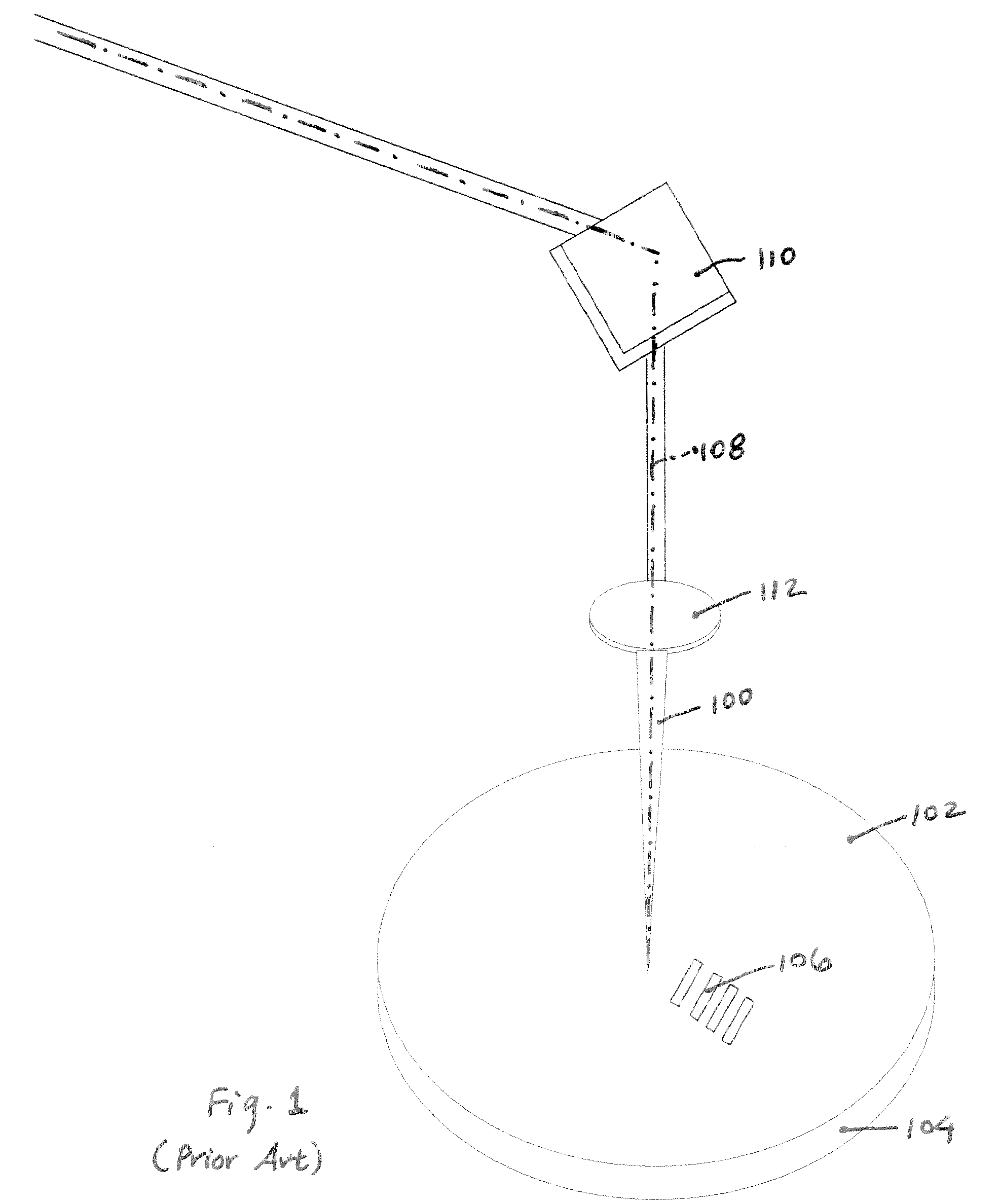
[0015]FIG. 1 depicts a pulsed laser beam 100 directed along a propagation axis toward the surface of a semiconductor wafer 102. Wafer 102 is positioned on a moveable support or stage 104. Features on the wafer surface include rows of target structures 106 to be processed by a laser beam 100. The location of a beam propagation axis 108 of laser beam 100 may be shifted relative to target structures 106 by controlling optical components such as mirrors 110 and lenses 112 capable of redirecting beam propagation axis 108, as well as through motion of support 104.

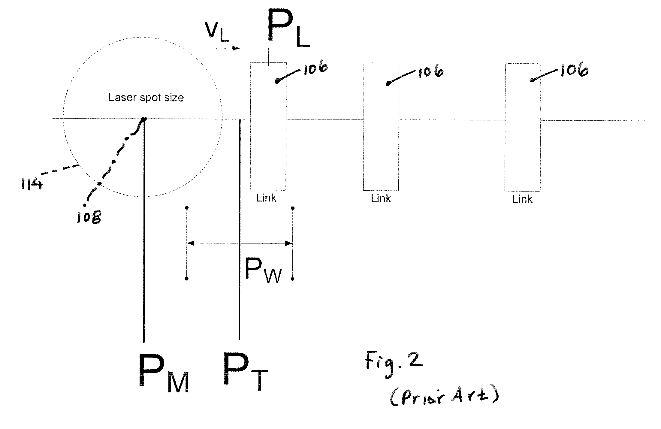
[0016]The comparative advantage of the PPT method over a standard triggering methodology based on measured position data is described below with reference to FIGS. 2 and 3 in connection with triggering the generation of a laser beam pulse in a link processing system. FIG. 2 depicts laser beam axis 108 moving along a row of target structures or links 106, in which some of links 106 are specified to be severed. Beam axis 108 define...


PUM

PropertyMeasurementUnit
Timeaaaaaaaaaa
Electrical conductoraaaaaaaaaa
Velocityaaaaaaaaaa

Abstract

A predictive pulse triggering (PPT) method enables precise triggering of a laser beam in a link-processing system. The PPT method entails triggering the laser beam based on estimated relative motion parameters of the target and laser beam axis. The PPT method allows for a six-fold improvement in laser positioning accuracy over the conventional, entirely measurement-based method.

Description

COPYRIGHT NOTICE[0001]© 2007 Electro Scientific Industries, Inc. A portion of the disclosure of this patent document contains material that is subject to copyright protection. The copyright owner has no objection to the facsimile reproduction by anyone of the patent document or the patent disclosure, as it appears in the Patent and Trademark Office patent file or records, but otherwise reserves all copyright rights whatsoever. 37 CFR § 1.71 (d).TECHNICAL FIELD[0002]The present disclosure concerns pulsed laser technology used to process target specimens.BACKGROUND INFORMATION[0003]Integrated circuits, especially those used in computer memory arrays, are often designed in repetitive patterns, employing a unit cell duplicated over a large area of a semiconductor chip. Manufacturing yields for such dense circuitry tend to be low, because there is a greater probability that particles or other defects will coincide with electrically active devices or interconnecting wires, rendering them ...

Claims


Application Information

Patent Timeline
IPC IPC(8): B23K26/02
CPCB23K26/034B23K26/038B23K26/04B23K26/063B23K2201/40B23K26/0648B23K26/08B23K26/4075B23K26/0643B23K26/0622B23K26/0344B23K26/40B23K2101/40B23K2103/50H01S3/00
Inventor BRULAND, KELLYVANDERGIESSEN, CLINT
Owner ELECTRO SCI IND INC
Why Eureka
Try Eureka