Power control method for secondary batteries

Active Publication Date: 2008-09-18
NGK INSULATORS LTD
View PDF5 Cites 108 Cited by
  • Summary
  • Abstract
  • Description
  • Claims
  • Application Information

AI Technical Summary

Benefits of technology

[0029]Since, in a power control method for secondary batteries of the present invention, the “demand responsive” group is further divided into a “delay responsive” group and an “instant responsive” group, input-output power subjected to a primary delay filter process out of the power to be input and output provided to the “demand responsive” group is distributed to the “delay responsive” group, and the remaining input-output power is distributed to the “instant responsive” group to control input-output power of the secondary batteries respectively depending on belonging group (a “delay responsive” group and an “instant responsive” group) in the preferable condition; the secondary batteries belonging to the “delay responsive” group are subjected to a primary delay filter process (flattening and smoothing) to be assigned to input and output (to charge and discharge) power where fluctuation is controlled (slowed down) in comparison with output fluctuation of the renewable power generator. Accordingly, the secondary batteries belonging to the “delay responsive” group have the reduced number of deduction, addition, and integration of measured battery current during charging and discharging in calculation of the state of charge, and thereby the error according to the operation is reduced to reduce a deviation between the actual state of charge of the secondary batteries and the control value. Thus, there hardly arises a problem of a sudden stop charging to preclude continuation of charge or a sudden stop discharging to preclude continuation of discharge of the secondary batteries, which causes a halt in the middle of compensation for output fluctuation of the renewable power generator.
[0030]Since, in a power control method for secondary batteries of the present invention, the “delay responsive” group is further divided into plural groups, plural powers subjected to a primary delay filter process with changing a time constant are distributed to each group to control input-output power of the secondary batteries respectively depending on belonging group in the preferable condition; power having controlled (slowed down) fluctuation in comparison with the large output fluctuation of the renewable power generator is distributed to a larger number of the secondary batteries with compensating output fluctuation of the renewable power generator to be able to input and output (charge and discharge). This enables to reduce number of deduction, addition, and integration of measured battery current during charging and discharging in calculation of the state of charge with respect to a larger number of secondary batteries, and thereby the error according to the operation is reduced to reduce a deviation between the actual state of charge of the secondary batteries and the control value in the larger number of secondary batteries. Therefore, there hardly arises a problem of a sudden stop charging to preclude continuation of charge or a sudden stop discharging to preclude continuation of discharge of the larger number of

Problems solved by technology

However, since the natural energy fluctuates every moment, a renewable power generator has an obstacle of inevitable fluctuation of output power toward spreading out.
However, a grid connection (power-generating) system where a renewable power generator is combined with a power storage compensator provided with plural secondary batteries as the main components has a problem as described below.
In this process, analog/digital conversion of the measured battery current is executed, and inevitable small error is generated by every conversion process.
The error is prone to increase as the number of the addition, deduction, and integration increases.
Therefore, fluctuation of input-output power of each secondary battery is frequently caused, and therefore the number of deducting, adding, and integrating increases to enlarge the error, which may cause large deviation between the actual state of charge and the control value.
When there is deviation between an actual state of charge an

Method used


Image

  • Power control method for secondary batteries
  • Power control method for secondary batteries
  • Power control method for secondary batteries

Examples


example

Example 1

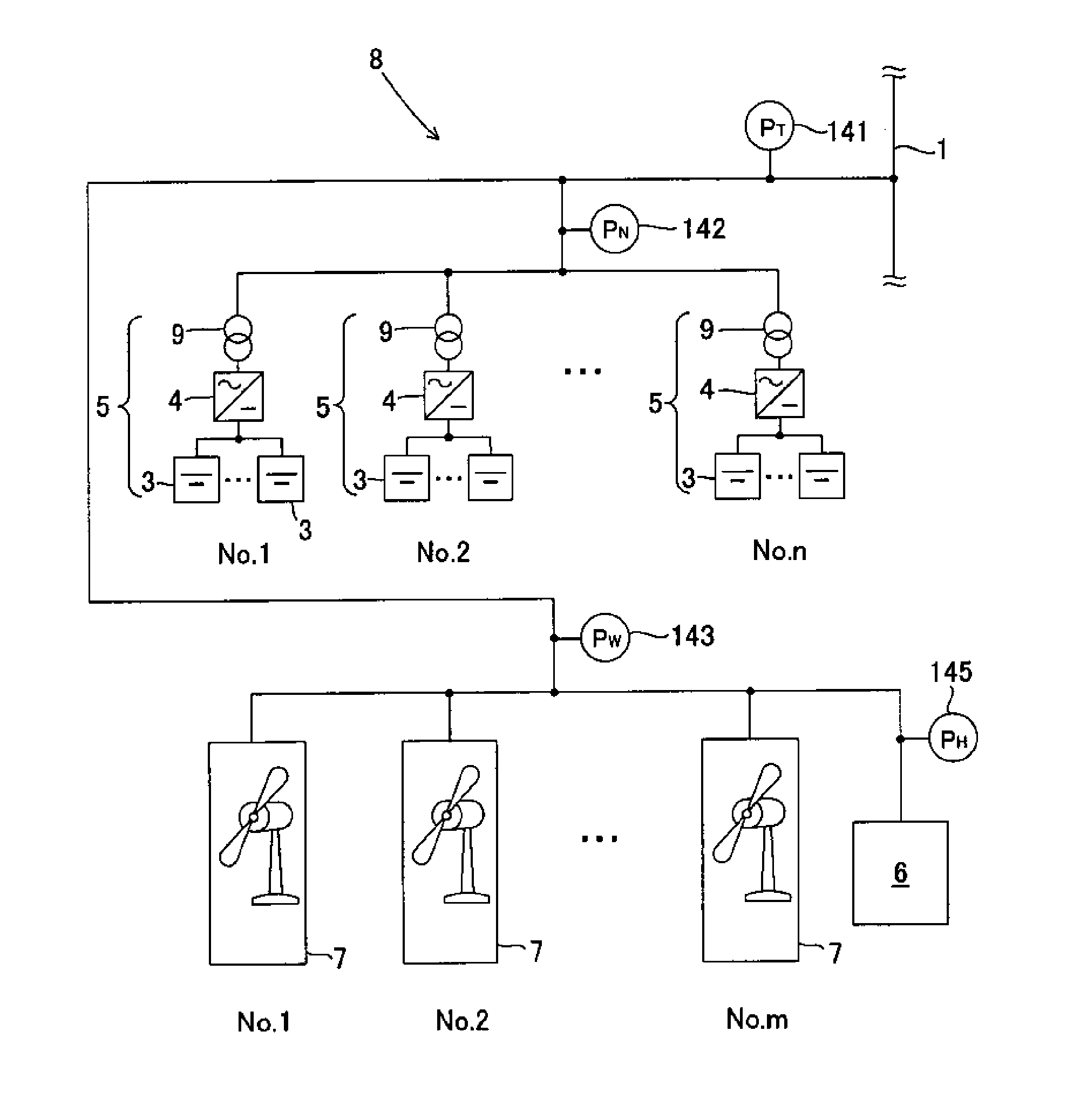
[0084]A grid connection system based on the grid connection system 8 shown in FIG. 1 was constructed to run a simulation of a power control method for secondary batteries of the present invention. Fifteen sodium-sulfur batteries each having a rated power of 2 MW (30 MW in total) and a wind power generator of a rated power of 51 MW were employed.

[0085]The operation plan value PP was changed on the time (section) basis to be set as in Table 1. The fifteen sodium-sulfur batteries were divided as shown in Table 2. With respect to the six sodium-sulfur batteries belonging to the “constant power control” group, the constant power control amount was distributed as shown in Table 2 on the time (section) basis.

TABLE 1No.Section (Sec.)Operation plan value PP (kW)1 0-1000 → 02100-200  0 → 450003200-50045000 → 450004500-60045000 → 0  5600-7000 → 0

TABLE 2Number ofGroup NamebatteriesParameter / setting“Instant2—responsive”group“Delay7Time constant 60 sec.responsive”group“Constant power6Tim...


PUM


Abstract

There is provided a power control method for secondary batteries constituting, in a grid connection system supplying electric power to a power system by combining a power generator where output power fluctuates with a power storage compensator, the power storage compensator and compensating fluctuation of output power of the power generator. The method includes the steps of: dividing the secondary batteries into a “constant power control” group and a “demand responsive” group, and distributing predetermined constant input-output power out of power to be input and output provided to all the secondary batteries in order to compensate fluctuation of output power of the power generator to the “constant power control group” and the remaining input-output power to the “demand responsive” group to control input-output power of the secondary batteries respectively depending on the belonging groups.

Description

BACKGROUND OF THE INVENTION AND RELATED ART STATEMENT[0001]The present invention relates to a power control method for secondary batteries in a grid connection system supplying electric power to a power system by combining a power generator such as wind power generator whose output power fluctuates with a power storage compensator having plural secondary batteries.[0002]In recent years, natural energy power generators (renewable power generator) generating electric power from wind power, solar light, geothermal heat, or the like, has been spotlighted and put to practical use. Since the renewable power generators are clean power generators which do not use the limited resources such as petroleum but use energy resources inexhaustibly present in nature and can inhibit carbon dioxide from being emitted, the number of companies, autonomies, and the like, which install renewable power generators is increasing from the viewpoint of prevention of global warming.[0003]However, since the nat...

Claims


Application Information

Patent Timeline
IPC IPC(8): H02J1/00H02J7/00
CPCH02J3/32H02J3/46Y02E70/30H02J3/383H02J3/382Y02E10/563Y02E10/566Y02E10/763H02J3/386H02J2300/28H02J2300/20H02J2300/24H02J3/381Y02E10/56Y02E10/76H02J3/466
Inventor FUKUHARA, MOTOHIRO
Owner NGK INSULATORS LTD
Why Eureka
Try Eureka