Optical system

Inactive Publication Date: 2008-09-18
OTO PHOTONICS
View PDF12 Cites 16 Cited by
  • Summary
  • Abstract
  • Description
  • Claims
  • Application Information

AI Technical Summary

Benefits of technology

[0009]It is one objective of the present invention to provide a diffraction grating for being applied to an optical system. The diffraction grating linearly distributes spectral components of all wavebands (including infrared, visible light and ultraviolet) on an image plane in accordance with the wavelength and can achieve desired image quality.
[0010]It is another objective of the present invention to provide an optical system with simple structure and microminiaturized volume that facilitates portability.
[0011]It is yet another objective of the present invention to provide an optical system, which can be mass-produced with reduced manufacturing costs and feasible for long-term use.

Problems solved by technology

However, such instruments are currently disadvantageous by: (a) bulkiness resulted in great cost and using limitedly at fixed locations, (b) time consumption for wideband spectrum measurement, and (c) demand for skilled operators because cautious operation is necessary.
Therefore, the applications of this prior spectrometric sensor are limited.
In such spectrometer, the photoelectric diode array is applied with limitations because the photoelectric diode array is substantially a flat plane, while the focuses of the spectrometer are distributed on a curved surface and, more particularly, on the Rowland circle.
However, this approach consumes large space and requires a large detector.
Although such approach can compromise the disadvantages of photoelectric diode array, problems such as energy lost and degraded resolution may also occur when the focused signals are led out by the optical fibers.
However, the above-mentioned inventions are all systems with complex structures and therefore fail to achieve the objective of microminiaturizing an optical system to become portable.

Method used


Image

  • Optical system
  • Optical system
  • Optical system

Examples


embodiment 1

[0040]A grating G1 is provided with a profile as shown in FIG. 9. The experiment conditions are referred to FIG. 8, wherein the entrance slit width s1=62.5 μm, the incident angle αc=75°, the incident arm length r1=30 mm, the diffraction order m=2, the grating interval d=3 μm, the grating G1 is placed on the x coordinate axis and the included angle θ between the planar detector D and the x coordinate axis is 69.3°. FIG. 10A exhibits the diffraction result of the grating G1, which is tested and derived by a ray-tracing software, Tracepro version 3.22, under these conditions. FIGS. 10B, 10C and 10D display the measuring results acquired by the detector D around 360 nm, 550 nm, and 720 nm, respectively. Thereupon, it is learned that the grating G1 reaches the resolution of 2 nm in the three wavelength ranges.

embodiment 2

[0041]A grating G2 is provided with a profile as shown in FIG. 9. The experiment conditions are referred to FIG. 8, wherein the entrance slit width s1=62.5 μm; the incident angle αc=75°, the incident arm length r1=30 mm, the diffraction order m=2, the grating interval d=3 μm, the grating G2 is placed on the x coordinate axis and the included angle θ between the planar detector D and the x coordinate axis is 80.5°. FIG. 11A exhibits the diffraction result of the grating G2, which is tested and derived by the ray-tracing software, Tracepro version 3.22, under these conditions. FIGS. 11B, 11C and 11D display the measuring results acquired by the detector D around 360 nm, 550 nm, and 720 nm, respectively. Thereupon, it is learned that the grating G2 reaches the resolution of 2 nm in the three wavelength ranges.

embodiment 3

[0042]A grating G3 is provided with a profile as shown in FIG. 9 and is in accordance with the Rowland circle. The experiment conditions are referred to FIG. 8, wherein the entrance slit width s1=62.5 μm, the incident angle αc=75°; the incident arm length r1=30 mm, the diffraction order m=2, the grating interval d=3 μm, the grating G3 is placed on the x coordinate axis and the included angle θ between planar detector D and the x coordinate axis is 73.64°. FIG. 12A exhibits the diffraction result of the grating G3, which is tested and derived by the ray-tracing software, Tracepro version 3.22, under these conditions. The resolution measurements are as illustrated in FIGS. 12B through 12D, wherein the resolution is not satisfying at the wavelength around 360 nm, and is perfect at the wavelength around 550 nm while the resolution is merely about 4 nm at the wavelength around 720 nm.

[0043]The comparison of the experiment results is tabled as Table 1. Therein, Φc is the included angle be...


PUM


Abstract

The invention concerns an optical system. The optical system comprises an input for receiving an optical signal, a predetermined output plane, and a diffraction grating for separating the optical signal received at the input into spectral elements thereof. The grating has a diffraction surface with a first predetermined profile. The first profile is formed by a plurality of points each conducted by different equations. Consequently, each spectral component is focused on the predetermined plane.

Description

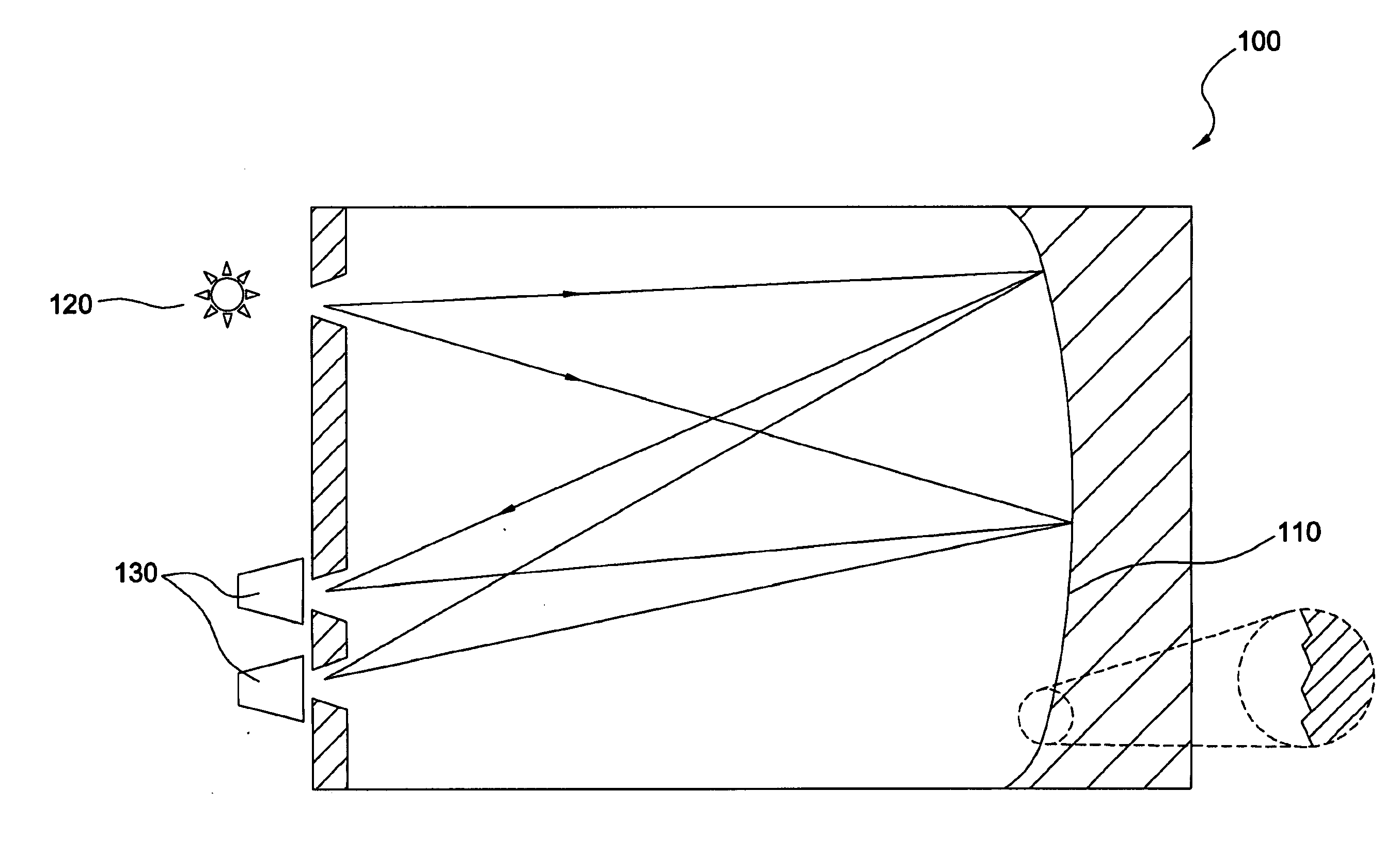
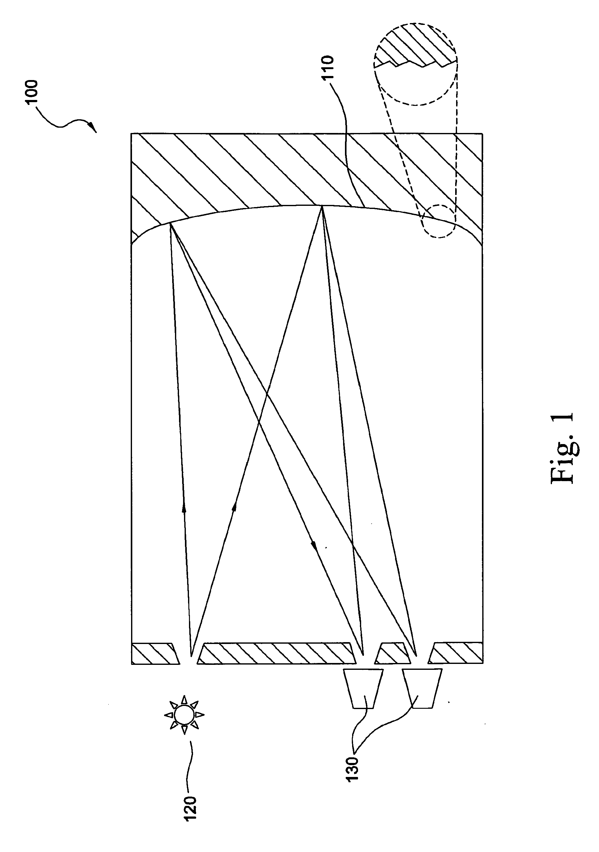
BACKGROUND OF THE INVENTION[0001]1. Field of the Invention[0002]The present invention relates to a novel diffraction grating and, more particularly, to a diffraction grating for being applied to an optical system.[0003]2. Description of the Related Art[0004]A spectrometer is typically implemented to measure photometry with regard to radiation sources, and a grating in such spectrometer is a component for dispersing a multi-frequency radiation. Instruments suchlike are extensively applied to deal with complex measurement tasks for acquiring accurate results. However, such instruments are currently disadvantageous by: (a) bulkiness resulted in great cost and using limitedly at fixed locations, (b) time consumption for wideband spectrum measurement, and (c) demand for skilled operators because cautious operation is necessary.[0005]U.S. Pat. No. 5,550,375 provides an infrared-spectrometric sensor 100 for gases, as shown in FIG. 1, which comprises a microstructured body having a reflecti...

Claims


Application Information

Patent Timeline
IPC IPC(8): G02B5/18G02B1/10G01J3/00
CPCG01J3/02G01J3/0218G01J3/0291G02B5/1861G01J3/1838G01J3/20G01J3/24G01J3/1804
Inventor KO, CHENG-HAO
Owner OTO PHOTONICS
Why Eureka
Try Eureka