Buckling restrained brace for structural reinforcement and seismic energy dissipation and method of producing same

a technology of structural reinforcement and restraint, which is applied in the direction of shock-proofing, other domestic objects, building components, etc., can solve the problems of building framing, facade and window damage, ceiling damage, etc., and achieves tailoring yield strength, high strain capacity, and a strong earthquake reducing

Inactive Publication Date: 2008-09-25
KAZAK COMPOSITES
View PDF15 Cites 41 Cited by
  • Summary
  • Abstract
  • Description
  • Claims
  • Application Information

AI Technical Summary

Benefits of technology

[0007]A buckling restrained brace (BRB) is provided with extremely high strain capability, and thus the ability to mitigate powerful earthquakes by accommodating and absorbing large inter-story drifts, and with the ability to tailor yield strength to a particular application. When compared to prior art steel BRBs, the present BRBs have demonstrated much higher drift performance and, through the use of an aluminum deforming core, superior acceleration performance. Methods of producing the BRBs are also provided.
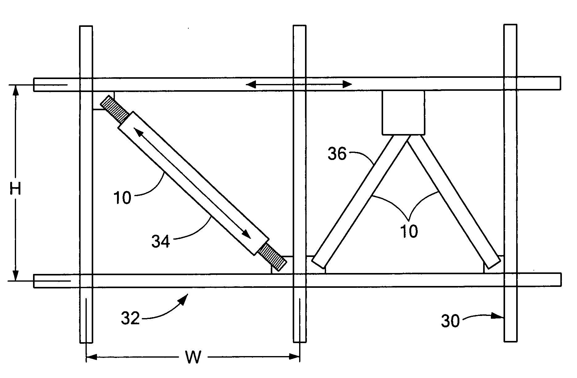
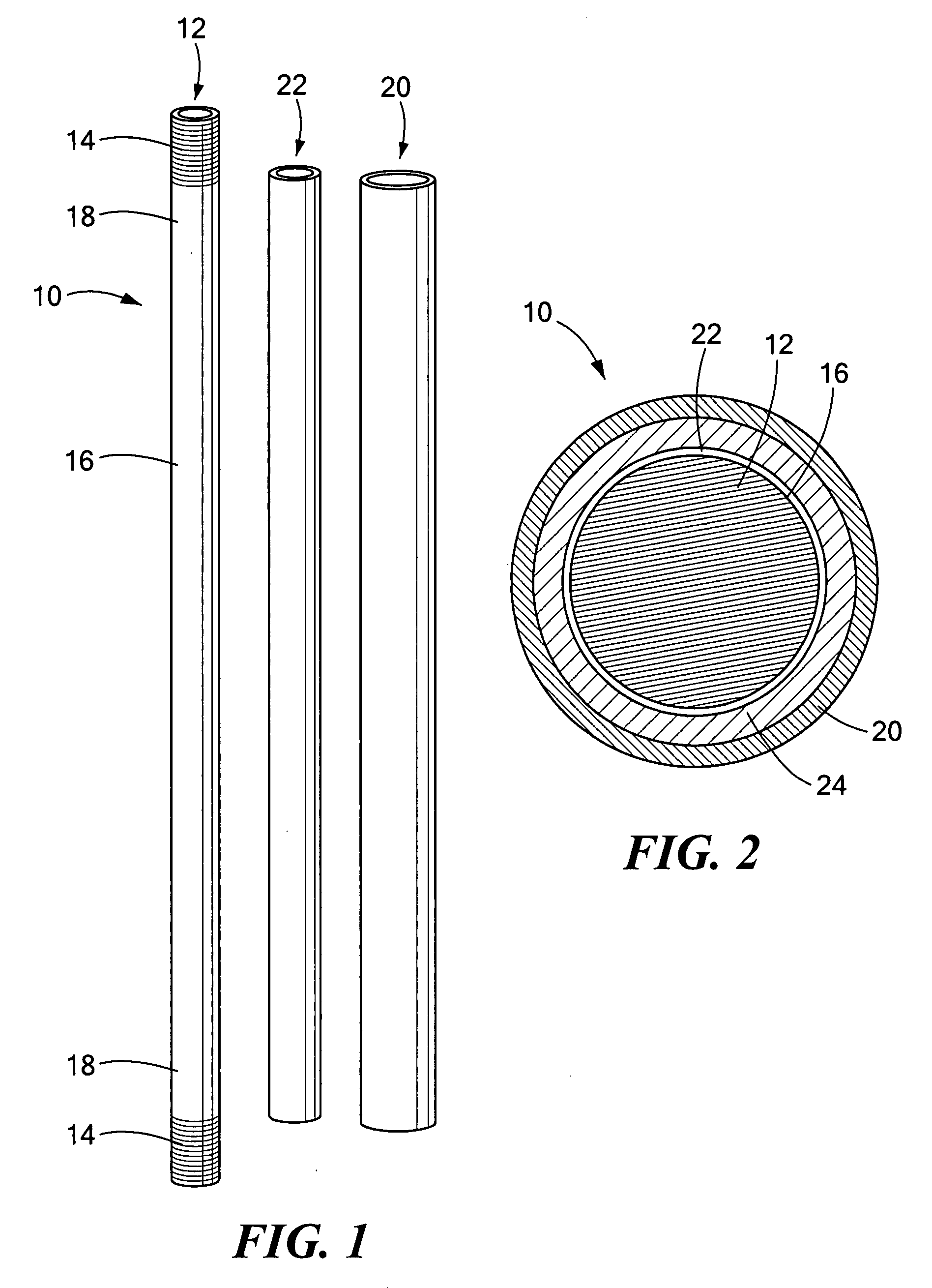
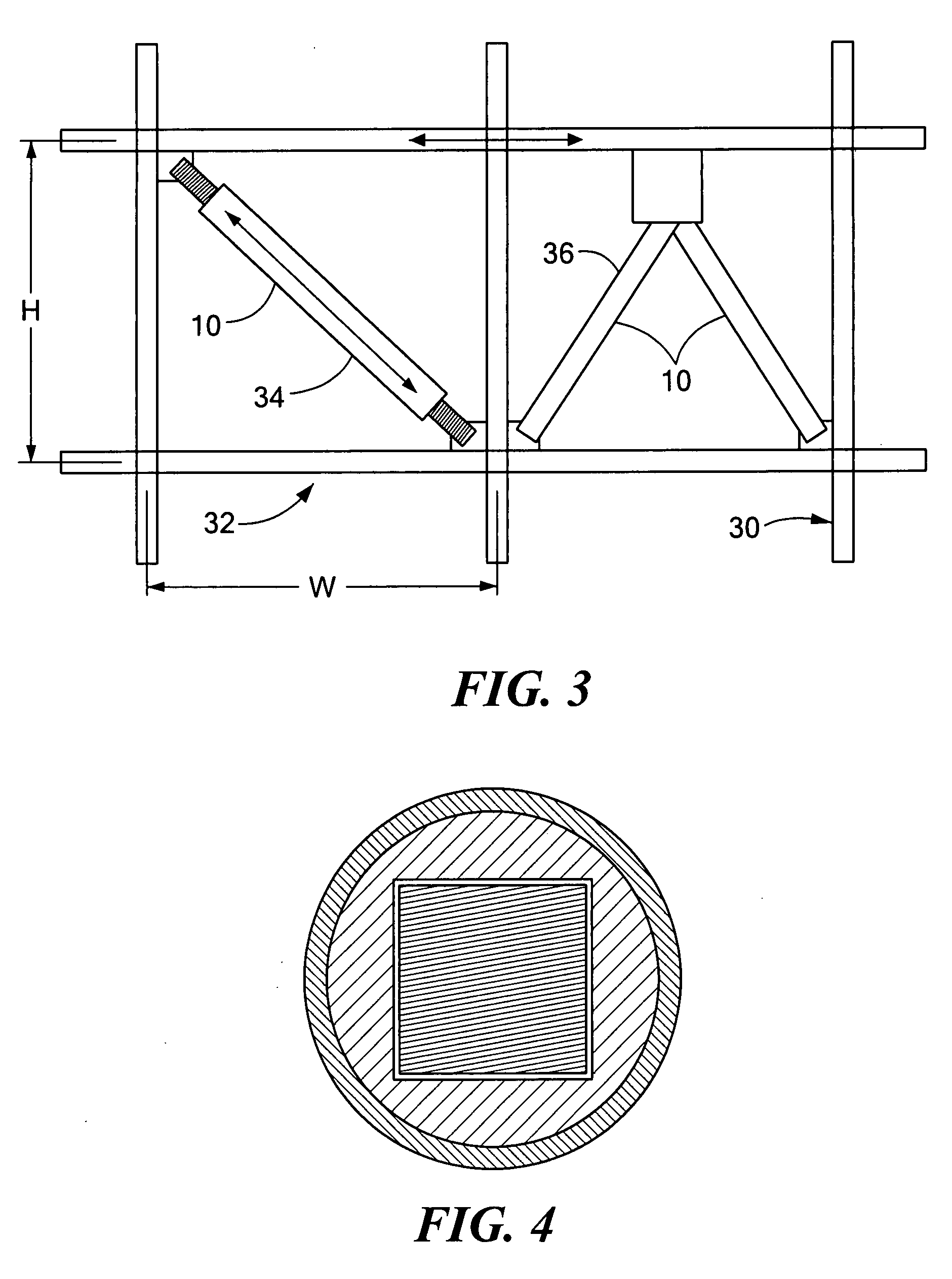
[0008]One embodiment of a buckling restrained brace includes a deformable core, such as a solid rod or bar, contained within a casing. The ends of the core protrude from the casing, so that the brace can be connected to a frame or other structure. A length of the deformable core between its ends, referred to as the gauge or yielding section, is capable of deforming plastically during an earthquake or blast loading. The gauge section is rendered weaker than the ends so that the gauge section has a lower yield strength than the ends. This can be accomplished by differentially heat treating (softening or averaging) the gauge section while keeping the ends heat insulated or by differentially heat treating (age-hardening) the ends of the deformable core while keeping the gauge section heat insulated. Additionally, the cross-sectional area of the gauge section relative to the ends may be reduced. The stronger ends connected to a structure do not fail during an earthquake or blast, while the gauge section yields. The casing or shell, such as a one-piece cylinder that can slide over the deformable core, provides containment of the core to prevent buckling of the core. A metal foil interface or other unbonding layer between the deformable core and the outer casing is provided so that the deformable core does not bind to the outer shell, and thus does not transfer axial load to the outer shell, while still being sufficiently constrained to prevent buckling. A filler material may optionally be provided between the core and the casing if desired.

Problems solved by technology

Inter-story drift causes damage to a building's framing, facade and windows.
Floor acceleration causes damage to ceilings, electrical systems, elevators, and building contents in general.

Method used


Image

  • Buckling restrained brace for structural reinforcement and seismic energy dissipation and method of producing same
  • Buckling restrained brace for structural reinforcement and seismic energy dissipation and method of producing same
  • Buckling restrained brace for structural reinforcement and seismic energy dissipation and method of producing same

Examples


example 1

[0039]A high capacity 2024 aluminum core, steel casing brace has been produced by differential heat treatment according to the invention. Using a core of 2024-T3 aluminum, the mid section was heated at 550 to 700° F. for 7 to 8 hours. The brace was tested in fully reversed tension-compression cycling. The testing sequence consisted of multiple cycles starting at low imposed displacements and increasing progressively to extremely high deformation (up to ±3.5% equivalent inter-story drift). See FIG. 10. This test demonstrates the capability of the present BRB to withstand deformations which would be imposed by a high magnitude earthquake. FIG. 10 shows that the BRB of the present invention subsequently survived multiple additional cycles at ±2.5% equivalent inter-story drift before ultimate failure.

example 2

[0040]A high capacity 6061 aluminum core, steel casing brace has been produced by differential heat treatment as in Example 1. The brace was tested in fully reversed tension-compression cycling to extremely high strains (up to ±3.5% equivalent inter-story drift) plus multiple additional cycles at ±2.5% equivalent inter-story drift before ultimate failure. See FIG. 11.

example 3

[0041]In another example, a 6061 aluminum core brace was produced, in which the ends of the core were heated at ˜370° F. for approximately 7 hours. The gauge section was held at a cooler temperature. The brace was tested in fully reversed tension-compression cycling.

[0042]FIG. 12 illustrates a comparison between demonstrated capabilities of different earthquake brace designs in fully reversed tension-compression loading. Maximum brace performance is plotted as percent deformation normalized by each respective brace's total installed length, i.e. including length of deforming core (gauge length) plus all transition sections, end fittings, and attachments to a building's steel frame. FIG. 12 shows that braces of the present invention have demonstrated strain capabilities (as shown in FIGS. 10 and 11) on the order of 50% to 100% greater than prior art, the latter being representative of braces in commercial use having a steel deforming core with cruciform cross-section and a concrete-f...


PUM

PropertyMeasurementUnit
thickaaaaaaaaaa
yield strengthaaaaaaaaaa
elongation capabilityaaaaaaaaaa

Abstract

A buckling restrained brace includes a deformable core contained within an outer casing. Ends of the core protrude from the casing for connection to a frame or other structure. A length of the deformable core between its ends, referred to as the gauge or yielding section, is capable of deforming during an earthquake or blast loading. The gauge section is differentially heat treated from the ends so that the gauge section has a lower yield strength than the ends. The casing provides containment of the core to prevent buckling of the core. A metal foil interface or unbonding layer is provided between the deformable core and the casing so that the deformable core does not bind to the casing. The buckling restrained brace provides significant performance improvements over prior art BRBs coupled with simplified assembly.

Description

STATEMENT REGARDING FEDERALLY SPONSORED RESEARCH OR DEVELOPMENT[0001]This invention was made under Department of the Army SBIR Contract #DACA42-02-C-0008. The government has certain rights in this invention.CROSS REFERENCE TO RELATED APPLICATIONS[0002]N / ABACKGROUND OF THE INVENTION[0003]During an earthquake or a blast from an explosion, a building is subjected to cyclic loading in the form of repeated tensile and compressive forces. Buckling restrained braces (BRBs), also known as unbonded braces, are finding acceptance as structural elements that add reinforcement and energy dissipation to steel frame buildings to protect the buildings against large deformations induced by earthquakes or blasts from explosions. The brace is designed to yield in tension or compression while resisting buckling.[0004]A prior art BRB employs a steel core and a steel casing. The steel core has a yielding segment, typically provided by a narrowed or necked region. The casing prevents buckling of the core...

Claims


Application Information

Patent Timeline
Patent Type & Authority Applications(United States)
IPC IPC(8): E04B1/98B21D47/00
CPCE04H9/021Y10T29/49623E04H9/028E04H9/0237
Inventor BYSTRICKY, PAVELFANUCCI, JEROME P.
Owner KAZAK COMPOSITES
Why Eureka
Try Eureka