Circularly Polarized Antenna and Radar Device Using the Same

a technology of circular polarization and radar, applied in the direction of polarised antenna unit combinations, resonant antennas, waveguide mouths, etc., can solve the problems of inability to obtain desired characteristics, unsuitable structurally for mass production, etc., to reduce radio interference, favorable circular polarization characteristics, favorable reflection characteristics

Inactive Publication Date: 2008-09-25
ANRITSU CORP +1
View PDF13 Cites 42 Cited by
  • Summary
  • Abstract
  • Description
  • Claims
  • Application Information

AI Technical Summary

Benefits of technology

[0091]In the circularly polarized antenna of the invention configured as described above, a cavity structure is formed such that metal posts penetrating the dielectric substrate are arranged so as to surround antenna elements. Moreover, rims/conducting rims which short-circuit the tips of the metal posts along the array direction, and which extend by a predetermined distance in the direction of the antenna elements are provided. Consequently, a surface wave can be prevented from being generated, which can provide an antenna with the desired radiation characteristic.
[0092]Further, in the circularly polarized antenna of the invention, a frequency characteristic of antenna gain can be provided with a sharp notch within the RR prohibited band by utilizing a resonance of the cavities, which is effective for reducing radio interference with the EESS described ab

Problems solved by technology

However, in the case of the antenna in the Non-Pat.
Document 4, a size of a dielectric is about λ/2, and when it is made to have an array structure, a plurality of blocks of the dielectrics must be set in array at constant distances, and it is not structurally suitable for mass production.
However, as described above, when a thic

Method used


Image

  • Circularly Polarized Antenna and Radar Device Using the Same
  • Circularly Polarized Antenna and Radar Device Using the Same
  • Circularly Polarized Antenna and Radar Device Using the Same

Examples


first embodiment

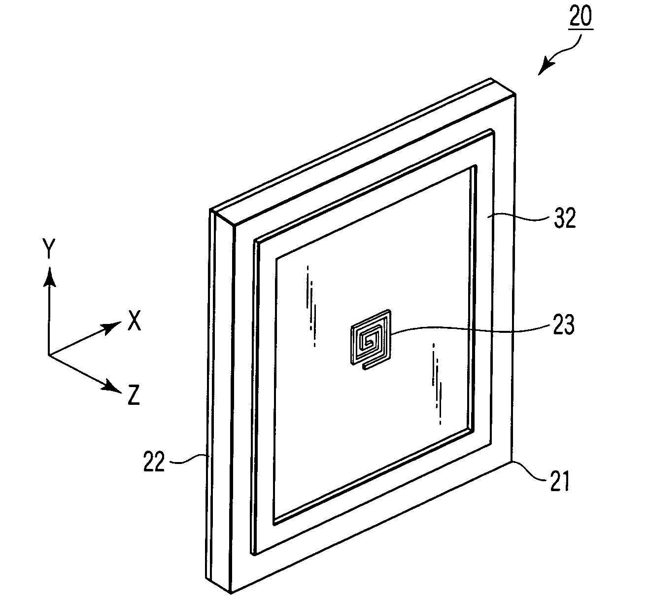
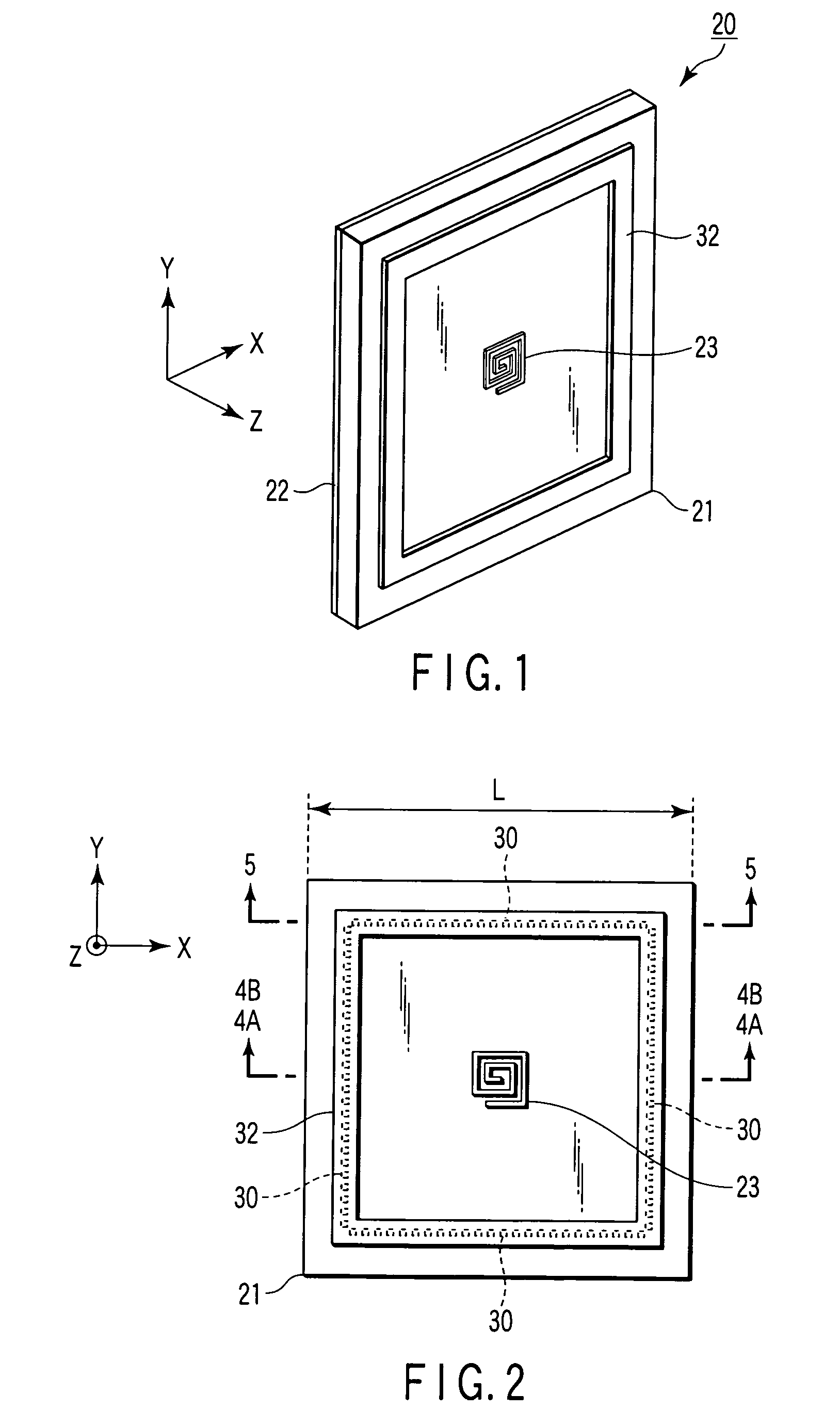
[0119]FIGS. 1 to 5 show a basic structure of a circularly polarized antenna 20 according to a first embodiment to which the present invention is applied.

[0120]Namely, FIG. 1 is a perspective view for explaining a configuration of the first embodiment of the circularly polarized antenna according to the invention.

[0121]FIG. 2 is a front view for explaining the configuration of the first embodiment of the circularly polarized antenna according to the invention.

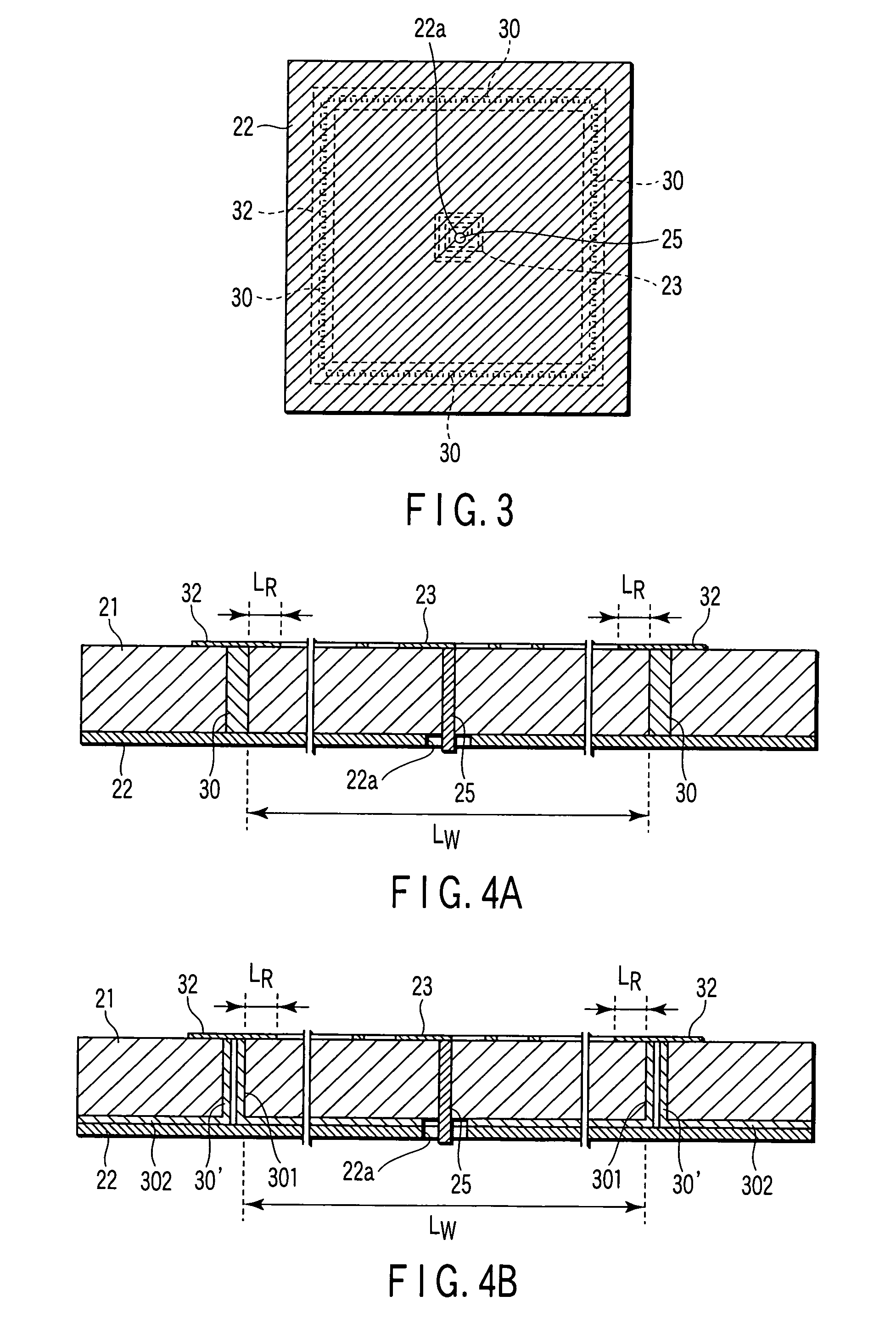
[0122]FIG. 3 is a rear view for explaining the configuration of the first embodiment of the circularly polarized antenna according to the invention.

[0123]FIG. 4A is an enlarged cross-sectional view taken along line 4A-4A of FIG. 2.

[0124]FIG. 4B is an enlarged cross-sectional view taken along line 4B-4B of FIG. 2.

[0125]FIG. 5 is an enlarged cross-sectional view taken along line 5-5 of FIG. 2.

[0126]The circularly polarized antenna according to the present invention basically has, as shown in FIGS. 1 to 5, a dielectric substrate 21...

second embodiment

[0167]In the circularly polarized antenna 20 of the above-described first embodiment, it suffices to set the above circularly polarized antenna 20 in an array when the gain required as a UWB radar or the like is insufficient, or when it is necessary to narrow a beam down.

[0168]Further, when the circularly polarized antenna is set in an array, a sequential rotation array shown in the following Non-Pat. Document 5 can be employed in which a wideband circular polarization characteristic and a wideband reflection characteristic are realized as an antenna overall by suppressing cross-polarization components.

[0169]Non-Pat. Document 5: Teshirogi, et al. “Wideband circularly polarized array antenna with sequential rotations and phase shift of elements”, Proc. of ISAP' 85, 024-3, pp. 117-120, 1985

[0170]A sequential rotation array is an array antenna with a plural number N of antenna elements having identical configuration arranged in identical plane, in which the respective antenna elements ...

third embodiment

[0212]FIG. 14 is a front view for explaining a configuration of a sequential rotation array to which a third embodiment of the circularly polarized antenna according to the present invention is applied.

[0213]As shown in FIG. 14, the circularly polarized antenna 20′ having the sequential rotation array structure to which the third embodiment of the circularly polarized antenna according to the invention is applied is configured as two sets of two-elemental sequential rotation arrays having identical configuration by the four antenna elements 23(1) to 23(4) and 23(5) to 23(8) respectively arrayed in a line vertically.

[0214]Namely, in the circularly polarized antenna 20′ shown in FIG. 14, an array angle of the antenna element 23(2) is rotated by π / 2 with respect to the antenna element 23(1), the antenna element 23(3) is made to have identical array angle as the antenna element 23(1), and the antenna element 23(4) is made to have identical array angle as the antenna element 23(2).

[0215]...


PUM


Abstract

A circularly polarized antenna has a dielectric substrate, a ground conductor which is piled up one surface side of the dielectric substrate, a circularly polarized type of antenna element formed on an opposite surface of the dielectric substrate, a plurality of metal posts whose respective one end sides are connected to the ground conductor and penetrate the dielectric substrate along a thickness direction thereof, and whose respective other sides extend up to the opposite surface of the dielectric substrate, the plurality of metal posts configuring a cavity by being provided at predetermined intervals so as to surround the antenna element, and a conducting rim which short-circuits the respective other end sides of the plurality of metal posts along an array direction thereof, and is provided so as to extend by a predetermined distance in a direction of the antenna element at the side of the opposite surface of the dielectric substrate. With the circularly polarized antenna, a radiation characteristic of the antenna can be made to be a desired characteristic by preventing a surface wave from being generated by means of the cavity and the conducting rim, and a frequency characteristic of the antenna gain can be made to have a sharp notch within the RR prohibited band by utilizing a resonance of the cavity. Accordingly, the circularly polarized antenna is effective for reducing radio interference with the EESS or radio astronomical services.

Description

TECHNICAL FIELD[0001]The present invention relates to a circularly polarized antenna which uses a technology for realizing high-efficiency, high-mass productivity and low-cost manufacturing, and a radar device using the same, and in particular, to a circularly polarized antenna which is suitable for ultra-wideband (UWB) radars used as automotive radars, and a radar device using the same.BACKGROUND ART[0002]It has been proposed to use UWB using a quasi-millimeter waveband of 22 to 29 GHz as automotive radars or portable short range radars (SRR).[0003]As an antenna of a radar device used within the UWB, not only a radiation characteristic thereof must be a wideband, but also it is necessary for the antenna to have a compact size and a thin, flat structure in consideration of the fact that it is provided, for example, in a gap between a vehicle body and a bumper at the time of being mounted on a vehicle.[0004]Further, as this antenna, low-loss and high-gain are required in order to car...

Claims


Application Information

Patent Timeline
IPC IPC(8): H01Q1/38H01Q1/36
CPCH01Q1/3233H01Q1/523H01Q21/24H01Q13/06H01Q13/18H01Q9/27
Inventor TESHIROGI, TASUKUHINOTANI, AYA
Owner ANRITSU CORP
Why Eureka
Try Eureka