High-Luminosity Stress-Stimulated Luminescent Material, Manufacturing Method Thereof, and Use Thereof

a luminescent material and high-luminosity technology, applied in the field can solve the problems of insufficient light emission luminescence, limited application and use and low light emission luminescence of stress-stimulated luminescent materials

Active Publication Date: 2008-09-25
NAT INST OF ADVANCED IND SCI & TECH
View PDF8 Cites 13 Cited by
  • Summary
  • Abstract
  • Description
  • Claims
  • Application Information

AI Technical Summary

Benefits of technology

[0022]A manufacturing method of a stress-stimulated luminescent material, which emits light in response to a mechanical stress, is characterized by controlling a structure to satisfy a condition to emit light based on at least one of: a luminescence mechanism using static electricity caused by friction; a luminescence mechanism using micro plasma caused by friction; a luminescence mechanism using a piezoelectric effect caused by strain a luminescence mechanism using lattice defect; and a luminescence mechanism using thermal generation.
[0023]The above-described manufacturing method is preferably arranged such that, to realize the luminescence mechanism using the piezoelectric effect caused by strain, raw materials are mixed and burned in such a manner as to form, in a base material included in the stress-stimulated luminescent material, a crystal structure with spontaneous polarization. It is also preferable that, to realize the luminescence mechanism u...

Problems solved by technology

The conventional stress-stimulated luminescent materials can effectively emit light by mechanical stress, but the light emission luminescence is sometimes insufficient.
The applications and uses of the stress-stimulated luminescent materials are therefore limited.
On the other hand, in case where the light intensity of outside light is as ...

Method used


Image

  • High-Luminosity Stress-Stimulated Luminescent Material, Manufacturing Method Thereof, and Use Thereof
  • High-Luminosity Stress-Stimulated Luminescent Material, Manufacturing Method Thereof, and Use Thereof
  • High-Luminosity Stress-Stimulated Luminescent Material, Manufacturing Method Thereof, and Use Thereof

Examples


example 1

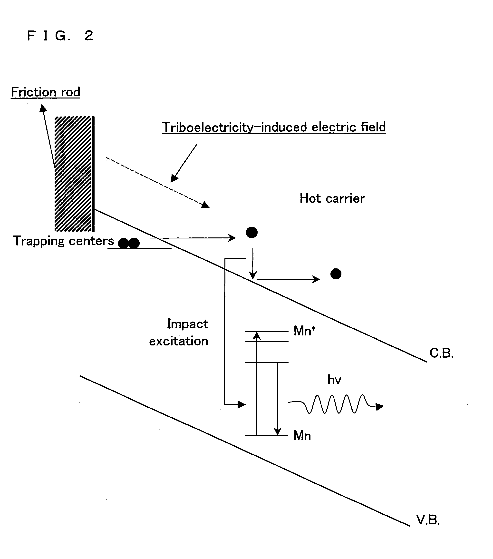
[0134]Among the stress-stimulated luminescent materials of the present invention, a material adopting the luminescence mechanism using friction will be specifically described in reference to FIGS. 3-12.

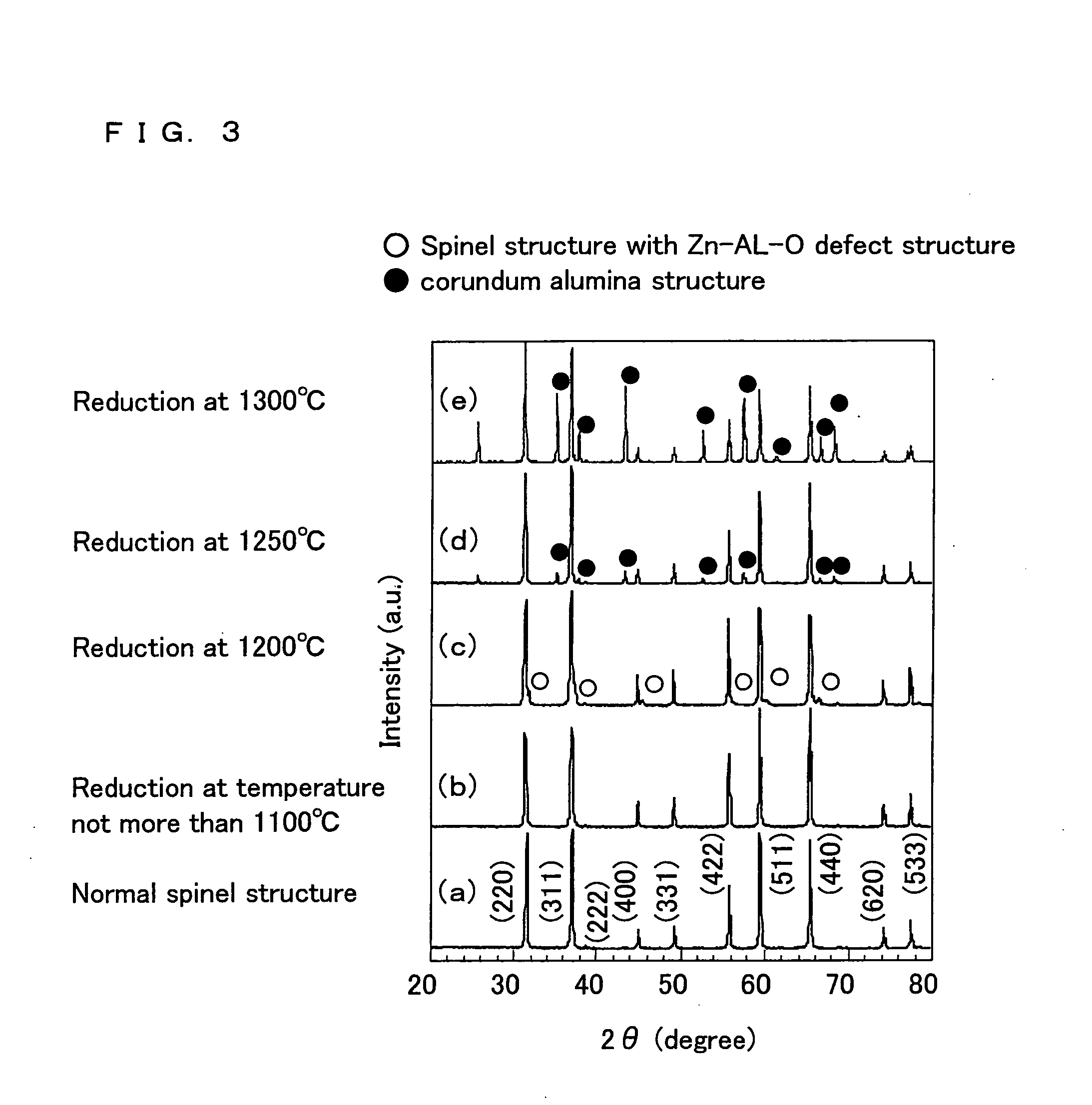
[0135]ZnO, Al2O3, and MnCO3 were weighed so as to satisfy Zn0.95Mn0.05Al2O4, and sufficiently mixed in ethanol. Then the mixed substances were dried and crushed. Subsequently, the substances were burned in the air at 1250° C. and for 8 hours, and a sample was obtained as a result. Analyzing the crystal structure of the sample using an X-ray diffractometer, it was found that a material with a pure spinel structure was obtained as shown in FIG. 3(a).

[0136]Thereafter, the obtained material (ZnAl2O4:Mn) with the spinel structure was reduced in 5% H2—Ar, at temperatures of 300-1300° C. FIG. 4 shows the weight loss curve during the reduction. The weight loss at temperatures not higher than 600° C. was caused by the desorption of adsorbed water and oxygen. The weight rapidly decreased at 120...

example 2

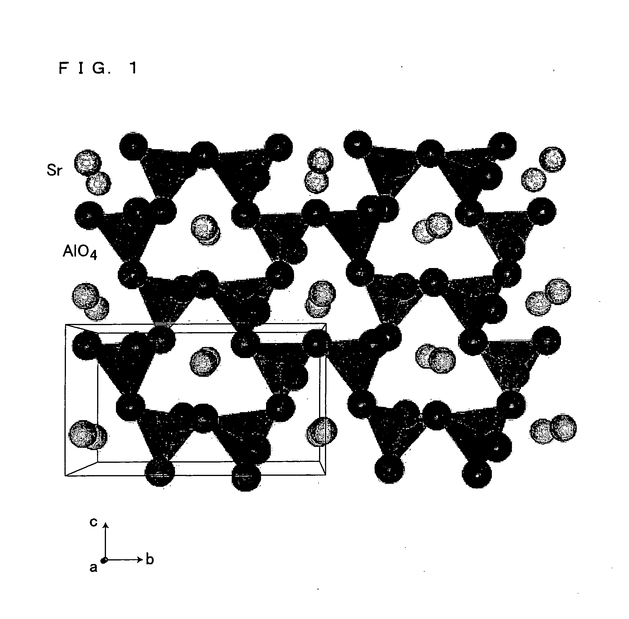
[0144]High purity reagents SrCO3, Al2O3, and Eu2O3 were weighed so as to satisfy Sr0.99Eu0.01Al12O19, Sr0.99Eu0.01Al4O7, Sr3.99Eu0.01Al14O25, Sr0.99Eu0.01Al2O4, and Eu0.01Sr2.99Al2O6, and were sufficiently mixed with one another. Thereafter, the mixed reagents were tentatively burned at 800° C. in the air, and then the burning was carried out at a temperature range of 1000-1700° C. and in the atmosphere of Ar+5% H2. As a result, stress-stimulated luminescent bodies with the aforesaid compositions were obtained. As a result of examining the crystal structure of each of the obtained stress-stimulated luminescent bodies by X-ray diffraction, it was found that the crystal structure was pure.

[0145]The obtained particulate (powder) stress-stimulated luminescence material was mixed with epoxy resin at a weight ratio of 1:1, and a rectangular-parallelepiped sample (i.e. a stress-stimulated luminescent body) of 54 mm, 19 mm, and 5 mm in length, width and height was formed.

[0146]Subsequently,...

example 3

[0150]In the same manner as Example 2, SrCO3, Eu2O3, and Al2O3 were mixed so as to have various compositions. As a result, a crystal phase coexisting with the α-SrAl2O4 phase was synthesized. FIGS. 14(a) and 14(b) shows the variations of stress-stimulated luminous intensities in case where the α-SrAl2O4 phase coexisted with a non-luminous crystal phase. The result proved that, even if stress-stimulated luminescence was achieved because of the coexistence of the α-SrAl2O4 phase, the luminous intensity was low. On the other hand, the highest luminous intensity was achieved when only the α-SrAl2O4 phase was provided. As shown in FIGS. 15 and 16, the luminous intensity in the case of the coexistence changed in accordance with the variation of the stress, and the luminescent spectrum was peaked at 520 nm, as in the case where only the α-SrAl2O4 phase was provided.


PUM


Abstract

The present invention provide a high-luminosity stress-stimulated luminescent material which emits visible light even in daylight, a manufacturing method thereof, and a typical example of the use thereof. The stress-stimulated luminescent material of the present invention satisfies conditions for light emission by at least one of: a luminescence mechanism using static electricity caused by friction; a luminescence mechanism using micro plasma caused by friction; a luminescence mechanism using a piezoelectric effect caused by strain; a luminescence mechanism using lattice defect; and a luminescence mechanism using thermal generation. For example, in case where a base material made of at least one type of aluminate is includes as the stress-stimulated luminescent material, the base material includes a crystal structure with spontaneous polarization, e.g. α-SrAl2O4, in order to realize the luminescence mechanism using the piezoelectric effect caused by strain.

Description

TECHNICAL FIELD[0001]The present invention relates to a stress-stimulated luminescent material which emits light in response to mechanical stress, a manufacturing method thereof, and the use thereof. The present invention particularly relates to a stress-stimulated luminescent material which is highly luminous and has a broader range of applications, a manufacturing method thereof, and a typical example of the use of the stress-stimulated luminescent material, such as a light emission method by which the stress-stimulated luminescent material effectively emits light.BACKGROUND ART[0002]Stress-stimulated luminescent materials which emits light in response to internal stress caused by a mechanical effect such as friction, shearing, impact, and vibration have conventionally been proposed. Known examples of the base material of such stress-stimulated luminescent materials include aluminate, silicate, and semiconductor found in nature. More specifically, for example, the inventors of the...

Claims


Application Information

Patent Timeline
IPC IPC(8): F21V9/16C09K11/54C09K11/08C09K11/64
CPCF21K2/04C09K11/643C09K11/0838C09K11/64
Inventor XU, CHAO-NAN
Owner NAT INST OF ADVANCED IND SCI & TECH
Why Eureka
Try Eureka