Condenser microphone chip

a condenser microphone and microphone chip technology, applied in the direction of electrostatic transducer microphones, transducer details, electrical transducers, etc., can solve the problems of disadvantages of difficult to ensure the uniformity of membranes, and few efforts to develop single-membrane silicon condenser microphones

Active Publication Date: 2008-09-25
GOERTEK MICROELECTRONICS CO LTD
View PDF15 Cites 52 Cited by
  • Summary
  • Abstract
  • Description
  • Claims
  • Application Information

AI Technical Summary

Benefits of technology

[0010]It is an object of the present invention to provide a condenser microphone chip having a curved beam which can alleviate at least a part of the above problems.
[0011]It is another object of the present invention to provide a condenser microphone chip having a curved beam which can effectively release residual stress in a diaphragm, prevent attachment or adhesion of the diaphragm to a backplate, and improve the reliability of condenser microphone chip.

Problems solved by technology

Few efforts are made to the development of single-membrane silicon condenser microphone.
However, the single-membrane silicon condenser microphone is disadvantageous because an edge of the diaphragm is connected to a peripheral portion.
However, requirements for a growing process of a membrane is strict and it is difficult to assure uniformity of the membrane if vibration performance of the diaphragm is improved only by making a material of low residual stress.
Since stress in the diaphragm is concentrated at an edge of the diaphragm due to the cantilever structure and the beam structure is often too soft, an adhesion problem is apt to occur.
With the free diaphragm structure, a microphone with a diaphragm of residual stress of zero can be obtained, but a process required for preparing the structure is complicated.
However, most of the above processes are complicated and are high in manufacturing cost.
An effective method is to make attachment or adhesion preventing protrusions, but it is necessary to increase a number of processing steps and thus cost.
With the above configuration, mechanical sensitivity makes great contribution to microphone sensitivity, but structure of the diaphragm is complicated.
In addition, because of the cantilever structure having 3 DOF (Dimension of Freedom), it is difficult to assure pose and reliability of the diaphragm.
The cantilever beams improve contribution of mechanical sensitivity to microphone sensitivity, but can not enable the diaphragm to translate.
In addition, with the above configuration, it is difficult to assure yield and reliability.

Method used


Image

  • Condenser microphone chip
  • Condenser microphone chip
  • Condenser microphone chip

Examples


first embodiment

[0119]The first embodiment according to the present invention will be described hereinafter with reference to FIGS. 1 through 6.

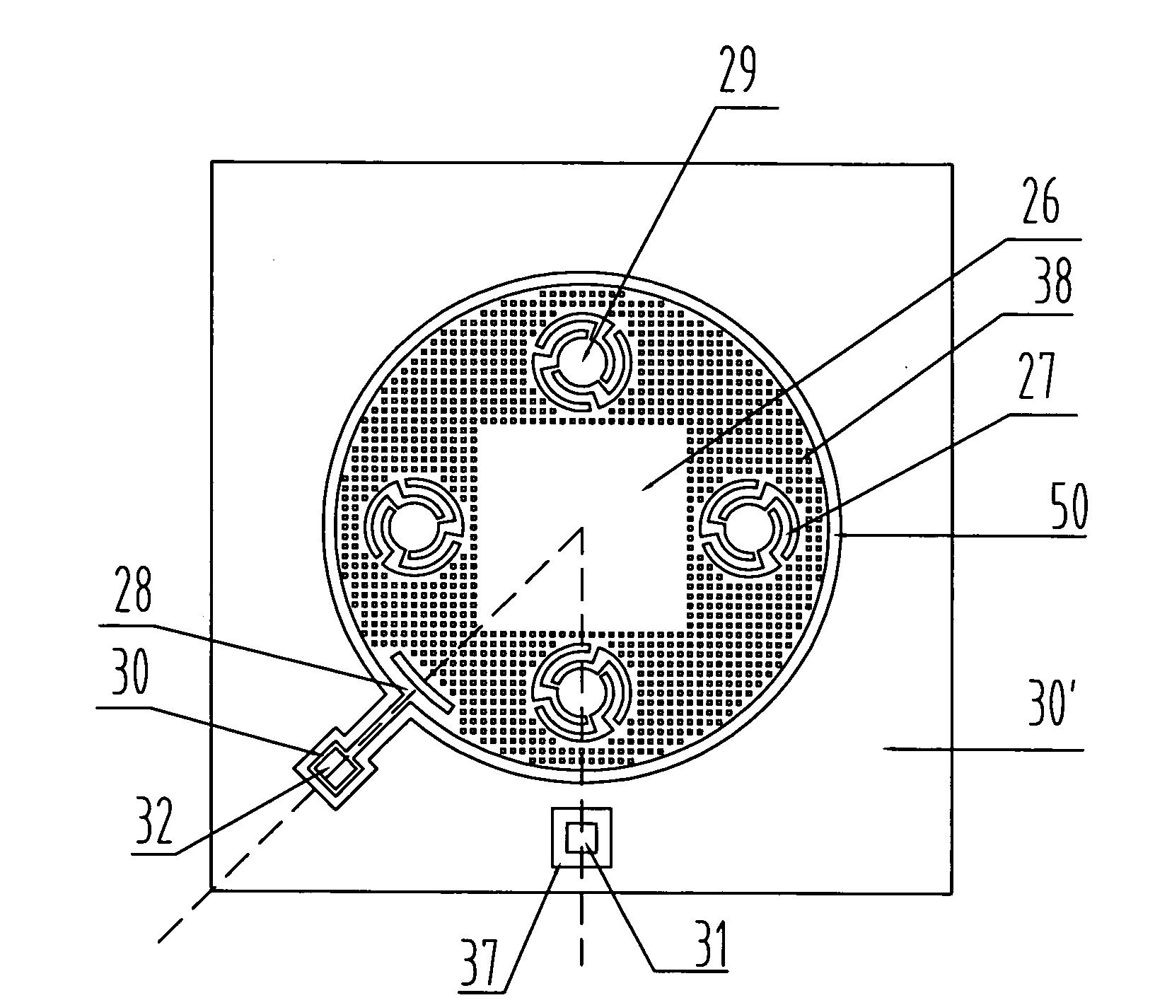
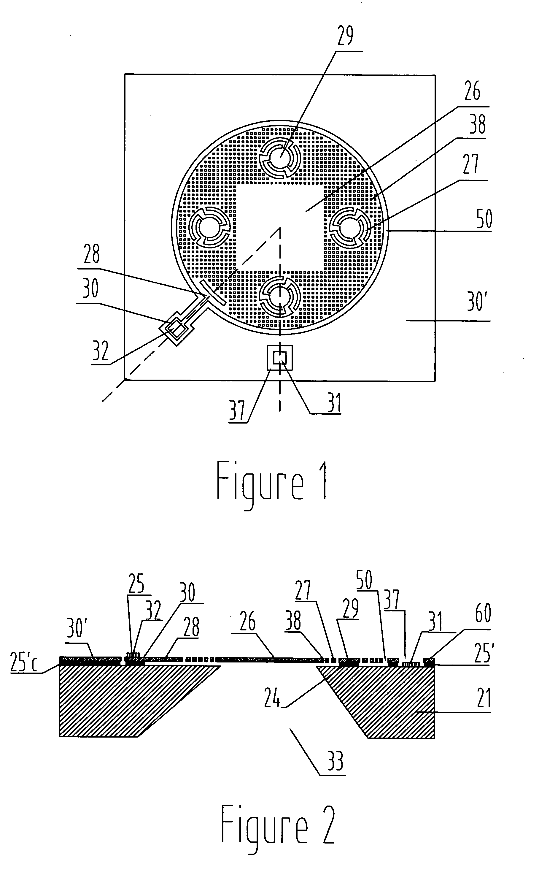
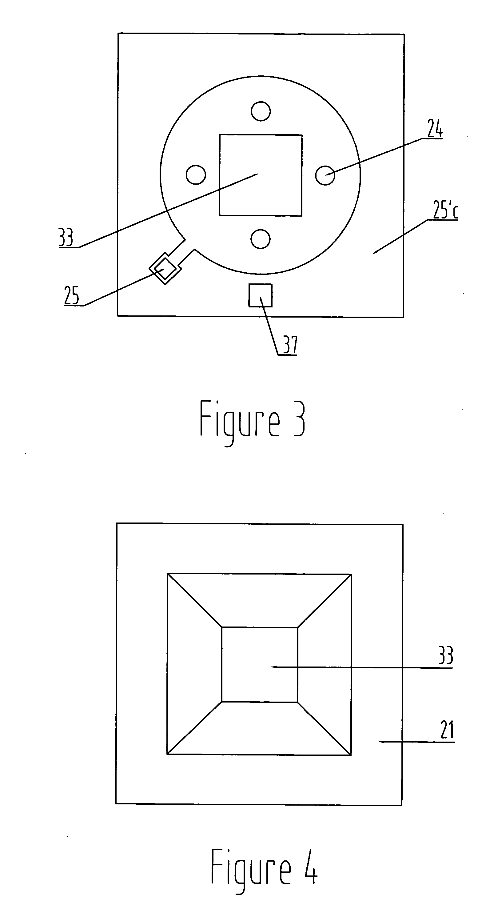
[0120]Referring to FIGS. 1 to 6, a condenser microphone chip according to a first embodiment of the present invention comprises: a substrate 21; a diaphragm 26 spaced from the substrate 21, for example, by a predetermined distance; and a curved beam 27 connected with the diaphragm 26 to anchor the diaphragm 26 to the substrate 21. The curved beam 27 may extend in one of a substantial “S” shape, a shape of a substantial arc, and a substantial helical shape. The curved beam 27 is illustrated as a beam extending in the “S” shape in FIG. 1. The condenser microphone chip may further comprise a dielectric layer 251 connected fixedly with or on a surface (an upper surface in FIG. 2) of the substrate 21, a conductive layer 60 (to be described in detail later) on a surface (an upper surface in FIG. 2) of the dielectric layer 25′; and a backplate side electrode 31 (t...

second embodiment

[0142]The second embodiment according to the present invention will be described hereinafter with reference to FIGS. 7 through 20.

[0143]Referring to FIGS. 7 to 20, a condenser microphone chip according to a second embodiment of the present invention comprises: a substrate 21; a backplate 23a connected with the substrate 21; a diaphragm 26 spaced from the backplate 23a, for example, by a predetermined distance; and a curved beam 27 connected with the diaphragm 26 to anchor the diaphragm 26 to the substrate 21. The diaphragm 26 and the backplate 23a may be formed of conductive layers. The backplate 23a may be suspended only at a center portion thereof. The condenser microphone chip may further comprise a dielectric layer 22 disposed on a surface (an upper surface in FIG. 8) of the substrate 21, a conductive layer 23 disposed on a surface of the dielectric layer 22, another dielectric layer 25′ disposed on a surface of the conductive layer 23, and a backplate side electrode 31 (to be d...

third embodiment

[0168]The third embodiment according to the present invention will be described hereinafter with reference to FIGS. 21 through 28 and 7 through 20.

[0169]Referring to FIGS. 21 to 28 and 7-20, a condenser microphone chip according to a third embodiment of the present invention comprises: a substrate 21 having a through hole 33; a backplate 23a connected with the substrate 21 and having a suspended region 23e opposing the through hole 33 of the substrate 21; a diaphragm 26 spaced from the backplate 23a, for example, by a predetermined distance; and a supporting member 24′ supported between the diaphragm 26 and the suspended region 23e. A predetermined region of the suspended region 23e around the supporting member 24′ has a stiffness lower than that of the other region of the suspended region 23e.

[0170]With the above configuration, the supporting member 24′ can prevent the diaphragm 26 from being attached to the backplate 23a, and at the same time resistance to vibration of the diaphr...


PUM


Abstract

Disclosed is a condenser microphone chip, comprising: a substrate (21); a diaphragm (26) spaced from the substrate; a curved beam (27) connected with the diaphragm (26) to anchor the diaphragm (26) to the substrate (21); a curved beam connecting part (29) having a shape of a substantially circular plate. The curved beam (27) is arranged in the diaphragm (26). The curved beam (27) includes a plurality of sub beams, each of the plurality of sub beams including a first sub beam portion extending in a substantially radial direction from a circumference of the curved beam connecting part (29); a second sub beam portion extending in a substantially circumferential direction from an end of the first sub beam portion away from the circumference of the curved beam connecting part (29) and having a shape of a substantial arc; and a third sub beam portion extending in the radial direction from an end of the second sub beam portion away from the first sub beam portion and connected to the diaphragm (26). The condenser microphone chip according to the present invention is high in sensitivity, low in noise, wide in frequency band, simple in manufacturing process, and high in reliability. In addition, the condenser microphone chip can be easily manufactured in mass production.

Description

BACKGROUND OF THE INVENTION[0001]1. Field of the Invention[0002]The present invention relates to a semiconductor condenser microphone chip.[0003]2. Description of the Related Art[0004]A condenser microphone chip is a capacitor composed of a diaphragm and a backplate. Currently, in most reports and patents a double-membrane capacitor structure which is manufactured by forming a diaphragm and a backplate on a silicon wafer by micromachining is adopted. Few efforts are made to the development of single-membrane silicon condenser microphone. A single-membrane silicon condenser microphone is reported in “Fabrication of Silicon Condenser Microphone Using Single Wafer Technology”, Journal of microelectromechanical systems, VOL. 1. No. 3, 1992, p 147-154. In the single-membrane silicon condenser microphone, a capacitor structure is formed by an edge portion of a diaphragm and a silicon substrate with the silicon substrate serving as a backplate and with a large hole at a center of the backp...

Claims


Application Information

Patent Timeline
Patent Type & Authority Applications(United States)
IPC IPC(8): H04R19/04
CPCH04R19/005H04R31/00H04R19/04
Inventor SONG, QINGLINTAO, YONGCHUNPANG, SHENGLILIU, TONGQING
Owner GOERTEK MICROELECTRONICS CO LTD
Why Eureka
Try Eureka