Method for treating optical fiber

a processing method and technology for optical fibers, applied in the direction of material analysis using wave/particle radiation, instruments, manufacturing tools, etc., can solve the problems of wasting time and money, unable to evaluate the hydrogen resistance characteristic of optical fibers, and the evaluation method is not suitable as a product evaluation method, etc., to improve the hydrogen resistance characteristic, confirm and improve the effect of deuterium processing

Inactive Publication Date: 2008-10-02
SHIN ETSU CHEM IND CO LTD
View PDF5 Cites 3 Cited by
  • Summary
  • Abstract
  • Description
  • Claims
  • Application Information

AI Technical Summary

Benefits of technology

[0028]Furthermore, in one exemplary processing method for an optical fiber, the predetermined value is a value obtained by adding 0.01 dB/km or more to the loss value at the time of starting the exposure of the optical fiber to the deuterium. According to this, it is possible to confirm the effective effect of the deuterium processing, without being exposed to influence of variation of an individual Rayleigh scatter coefficient A for the optical fiber being the monitoring target. Note that when a value in which the increase in loss value is lower than 0.01 dB/km is selected, the effect of the deuterium processing is small, and it is not possible to obtain significant improvement in hydrogen resistance characteristic.
[0029]Still further, in one exemplary pr...

Problems solved by technology

This further means that it takes about 3 weeks before being able to evaluate the hydrogen resistance characteristic of the optical fiber.
Consequently, such an evaluation method is not suitable as a product evaluation method for use during industrial optical fiber production processes.
Moreover, according to this method, it becomes necessary to cut off a measurement sample of a length of 1 km or above from an optical fiber to be evaluated, and the evaluation sample is doomed to be discarded after the evaluation.
This will reduce the real yield ratio of the product, which constitutes another reason why this evaluation method is not suitable for industrial application.
However, the test operation for the hydrogen resistance evalua...

Method used


Image

  • Method for treating optical fiber
  • Method for treating optical fiber
  • Method for treating optical fiber

Examples


first embodiment example

[0036]An optical fiber having a small WP is manufactured, and a length of 25 km from the optical fiber is wound to a spool as an evaluation sample. In addition, from the same optical fiber, a length of 2 km of a preliminary evaluation sample is cut off, for use in an effect measurement of the deuterium processing detailed later. Furthermore, from the same optical fiber, a length of 2 km of optical fiber is further cut off and stored as a comparison sample.

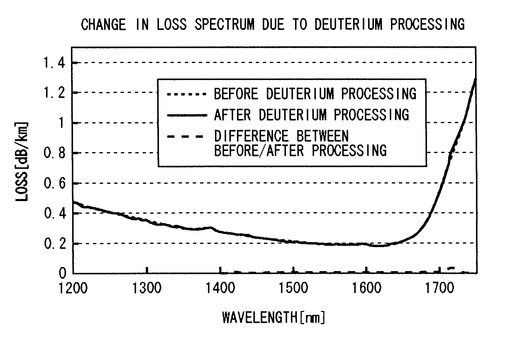
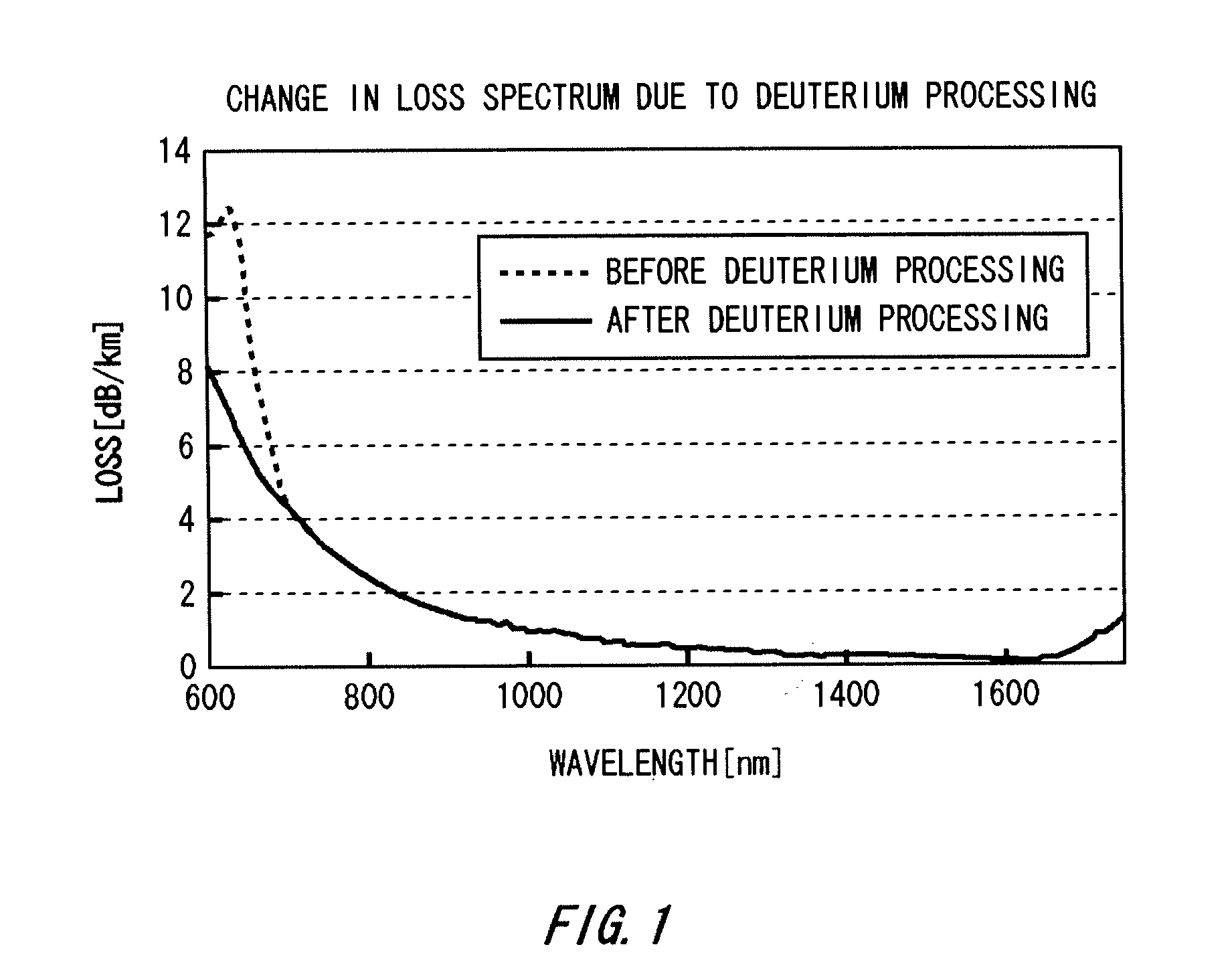
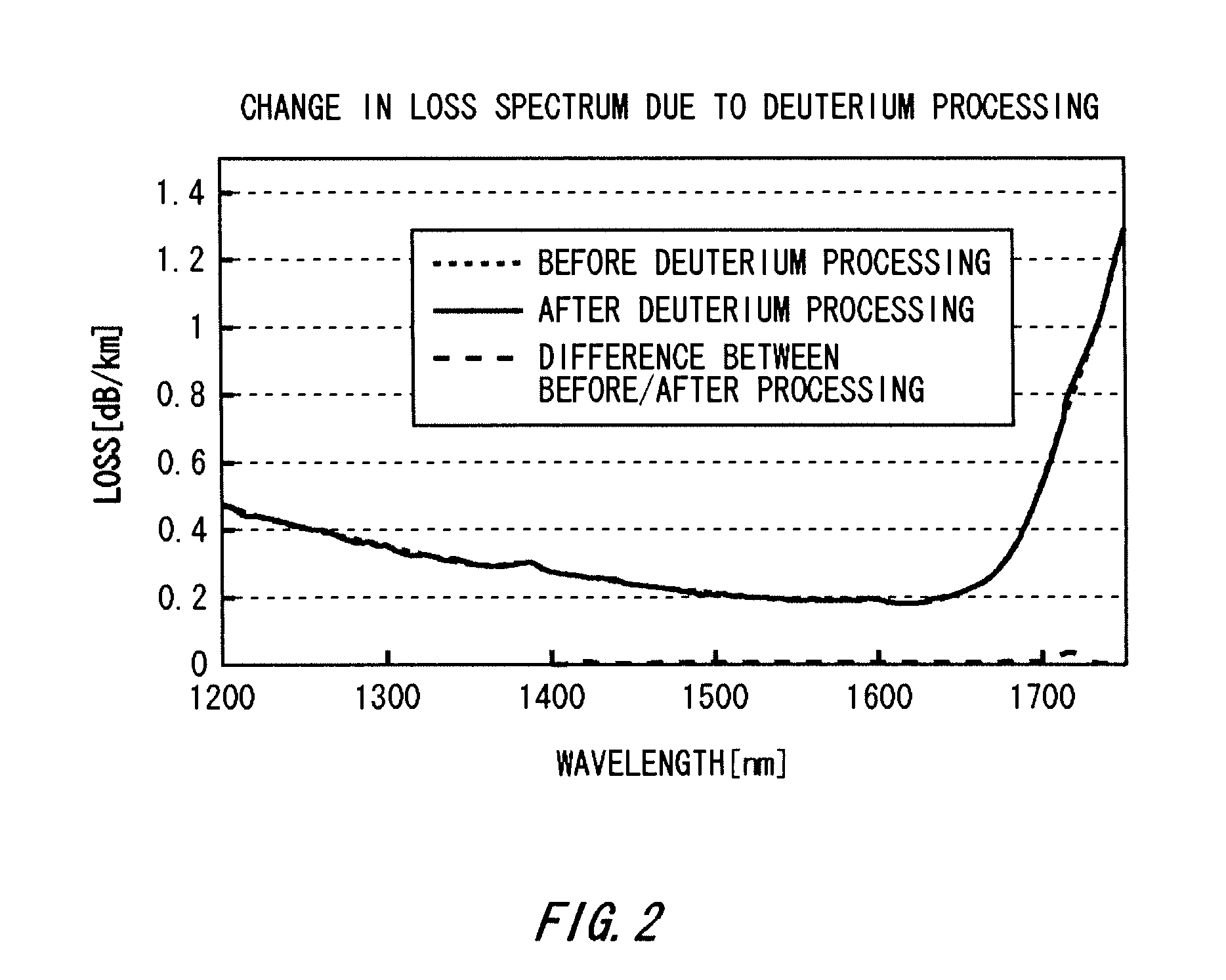
[0037]Prior to the deuterium processing, the loss spectrum of each of the evaluation sample and the preliminary evaluation sample is measured. At the wavelength of 630 nm, a large absorption loss peak of 6 dB / km is measured for a preliminary evaluation sample having a length of 2 km. In contrast, for an evaluation sample having a length of 25 km, the loss at 630 nm was too large and so the loss per unit length could not be measured. The loss at the wavelength of 1714 nm was measured to be 0.750 dB / km, for both of the evaluation sam...

second embodiment example

[0045]An evaluation sample having a length of 25 km and a preliminary comparison sample having a length of 2 km were prepared. The deuterium processing was conducted thereto under the same condition as in the first embodiment example, except for setting the change quantity of loss at the wavelength of 1714 nm at the time of ending the deuterium processing to be 0.03 dB / km. After the samples were exposed to the deuterium atmosphere for about 4 days, the loss at 1714 nm being the target of monitoring has reached 0.780 dB / km, and the change quantity has exceeded 0.03 dB / km, and so the deuterium processing was ended.

[0046]The loss spectrum was measured for the preliminary evaluation sample having a length of 2 km. The result shows a great loss reduction in the vicinity of the wavelength of 630 nm. In addition, an evaluation test was conducted to the preliminary evaluation sample according to a method prescribed in IEC 60793-2. The result shows no increase in WP. These confirm that an op...


PUM

PropertyMeasurementUnit
Nanoscale particle sizeaaaaaaaaaa
Wavelengthaaaaaaaaaa

Abstract

Included are monitoring a loss value of the optical fiber with respect to propagation light having a wavelength at or in the vicinity of 1714 nm after the optical fiber is exposed to deuterium; and ending the exposure of the optical fiber to the deuterium when a change quantity of the loss value has exceeded a predetermined value. The monitoring of the loss value is pursued by, while exposing the optical fiber to an atmosphere that contains deuterium, causing propagation light having a wavelength at or in the vicinity of 1714 nm to be incident from one end of the optical fiber, monitoring the propagation light emitted from the other end of the optical fiber, and measuring a loss value of the optical fiber. According to this, it is possible to manufacture an optical fiber having an excellent hydrogen resistance characteristic assuredly and at low cost.

Description

CROSS REFERENCE TO RELATED APPLICATION[0001]This is a continuation application of PCT / JP2006 / 308232 filed Apr. 19, 2006 which claims priority from Japanese Patent Application No. 2005-182468 filed Jun. 22, 2005, the contents of which are incorporated herein by reference.BACKGROUND[0002]1. Technical Field[0003]The present invention relates to a processing method of an optical fiber. In more detail, the present invention relates to a processing method for improving a hydrogen resistance characteristic of an optical fiber employed for a transmission medium of an optical signal.[0004]2. Related Art[0005]In an optical fiber, the peak (hereinafter referred to as “WP”) of an absorption loss attributable to the OH-group in the optical fiber lies in the band of a wavelength of 1383 nm. For this reason, in optical communication using an optical fiber as a transmission medium, a wavelength band around 1400 nm is not used as a signal wavelength. However, as a communication technology such as CW...

Claims


Application Information

Patent Timeline
IPC IPC(8): C03B37/018
CPCC03C13/047C03C25/607G02B6/02G02B6/00
Inventor INOUE, DAI
Owner SHIN ETSU CHEM IND CO LTD
Why Eureka
Try Eureka