Dye sensitized solar cell module and manufacturing method thereof

a solar cell module and sensitized technology, applied in the direction of cell components, final product manufacturing, sustainable manufacturing/processing, etc., can solve the problems of increasing the number of module fabricating steps, increasing the manufacturing cost of both the module structures shown in fig. 1a, b>1/b>b and b>2/b>, and the output voltage is relatively low. , to achieve the effect of high photoelectric conversion efficiency, high cell numerical aperture, and improved structur

Inactive Publication Date: 2008-10-02
SHINKO ELECTRIC IND CO LTD
View PDF3 Cites 35 Cited by
  • Summary
  • Abstract
  • Description
  • Claims
  • Application Information

AI Technical Summary

Benefits of technology

[0026]It is an object of the invention to provide a dye sensitized solar cell module which has a high cell numerical aperture and a high photoelectric converting efficiency, and at the same time, has a structure improved to fabricate a plurality of cells on a single substrate in a batch without requiring a complicated step, and a method of manufacturing the dye sensitized solar cell module.

Problems solved by technology

Practically to say, however, its output voltage is relatively low because a photoelectric converting efficiency of dye sensitized solar cell is far below the level of a silicon solar cell.
However, there is a problem in that the manufacturing costs of both the module structures shown in FIGS. 1A, 1B and 2 are increased due to an increase in the number of module fabricating steps and the complicated fabrication steps.
However, a method of forming an insulating barrier and an electrode connecting portion between adjacent cells does not show any concrete embodiment and might not be practical in use.
Therefore, in such an arranged cell, it is impossible to avoid a reduction in a photoelectric converting efficiency.
Therefore, it is impossible to avoid the reduction in the photoelectric converting efficiency as the whole dye sensitized solar cell module 300.

Method used


Image

  • Dye sensitized solar cell module and manufacturing method thereof
  • Dye sensitized solar cell module and manufacturing method thereof
  • Dye sensitized solar cell module and manufacturing method thereof

Examples


first embodiment

[0063]FIGS. 4A to 4C show the example of sectional structures of a dye sensitized solar cell module according to a preferred embodiment of the invention.

[0064]A dye sensitized solar cell module 401 according to the invention shown in FIG. 4A is constituted by arranging a plurality of dye sensitized solar cells 410 on a plane basis and connecting them in series with an intercell region 415 interposed therebetween.

[0065]A first transparent substrate 412, a first transparent conductive film 414, a dye carrying oxide semiconductor layer 416, an electrolyte layer 418, a catalyst layer 424, a second transparent conductive film 420 and a second transparent substrate 422 are laminated.

[0066]The first transparent substrate 412 and the second transparent substrate 422 are continuous single substrates which are common to all of the dye sensitized solar cells 410, respectively.

[0067]The first transparent conductive film 414 is constituted by an electrode portion 414E provided in the cell 410 an...

second embodiment

[0071]FIGS. 5A to 5C show the examples of sectional structures of a dye sensitized solar cell module according to a further preferred embodiment of the invention.

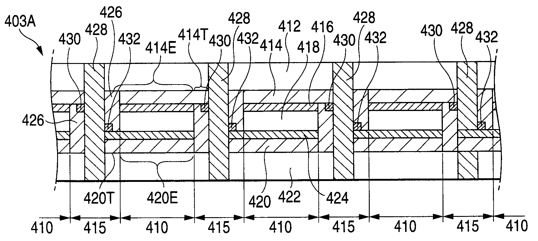
[0072]Dye sensitized solar cell modules 401A, 402A and 403A shown in FIGS. 5A, 5B and 5C have features that a first auxiliary conductive layer 430 and a second auxiliary conductive layer 432 are added to the extended portion 414T of the first transparent conductive film 414 and the extended portion 420T of the second transparent conductive film 420 which are connected to the electrode connecting portion 428 respectively in the structures of the dye sensitized solar cell modules 401, 402 and 403 shown in FIGS. 4A, 4B and 4C.

[0073]In the embodiment shown in FIG. 5A (a configuration in which an electrode connecting portion 428 penetrates through a second transparent substrate 422 on a catalyst layer 424 side and is exposed), the first auxiliary conductive layer 430 is added to compensate for a thickness of the first transparen...

example 1

Example of Manufacture of Structure According to the First Embodiment

[0077]The dye sensitized solar cell module according to each of the embodiments shown in FIGS. 4A, 4B and 4C can be manufactured by the same method. A manufacturing method will be described below by setting the case of the embodiment shown in FIG. 4A to be a typical example. FIG. 6A to FIG. 12D sequentially show the manufacturing steps thereof.

[0078]First of all, as shown in a section of FIG. 6A, a first transparent conductive film 414 is formed over a whole surface of a first transparent substrate 412. It is possible to use a product put on the market (A110U80 manufactured by Asahi Glass Company) in a state in which the FTO (fluorine-doped tin oxide) film 414 is formed on the glass substrate 412. A thickness of the first transparent conductive film 414 is equal to or greater than 0.1 μm and is usually approximately 0.3 to 2 μm.

[0079]For the first transparent conductive film 414, SnO2 (tin oxide), ATO (antimony-dop...


PUM

PropertyMeasurementUnit
thicknessaaaaaaaaaa
thicknessaaaaaaaaaa
widthaaaaaaaaaa

Abstract

In a solar cell module in which a plurality of dye sensitized solar cells is arranged on a plane basis and is connected in series with an intercell region interposed therebetween, a first transparent substrate, a first transparent conductive film, a dye carrying oxide semiconductor layer, an electrolyte layer, a catalyst layer, a second transparent conductive film and a second transparent substrate are laminated, an insulating barrier seals cells on both sides thereof in fluid tightness and insulates them in the intercell region, an electrode connecting portion provided in a central part in a vertical direction of the insulating barrier connects an extended portion of the first transparent conductive film of one of the cells on the both sides to that of a second transparent conductive film of the other cell, and the electrode connecting portion penetrates through at least one of the first transparent substrate and the second transparent substrate in the vertical direction and is thus exposed.

Description

BACKGROUND OF THE INVENTION[0001]1. Field of the Invention[0002]The present invention relates to a dye sensitized solar cell module and a method of manufacturing the dye sensitized solar cell module, and more particularly to a dye sensitized solar cell module which has a high cell numerical aperture and a high photoelectric converting efficiency, and at the same time, has a structure improved to fabricate a plurality of cells on a single substrate in a batch without requiring a complicated step, and a method of manufacturing the dye sensitized solar cell module.[0003]2. Description of the Related Art[0004]A dye sensitized solar cell is proposed such as represented by Gretzel's patent, Japanese Patent No. 2664194 and Japanese Patent No. 2101079. As compared with a silicon solar cell, material is more inexpensive and does not require large-scaled manufacturing equipment. Therefore, such a dye sensitized solar cell is advantageous for a small-scaled power supply source at a low cost.[0...

Claims


Application Information

Patent Timeline
Patent Type & Authority Applications(United States)
IPC IPC(8): H01L31/042H01L31/18H01M50/528
CPCH01G9/2031H01G9/2059H01G9/2068Y02E10/542Y02P70/50
Inventor ICHIKAWA, SUMIHIROTAKEI, KOJISHIMIZU, NORIYOSHISUZUKI, YASUNARIFUKASAWA, RYOMATONO, DAISUKESHIMIZU, YUICHIRO
Owner SHINKO ELECTRIC IND CO LTD
Why Eureka
Try Eureka