
Heat-insulating container and method for manufacturing same

Inactive Publication Date: 2008-10-02
NICHIAS CORP
View PDF19 Cites 9 Cited by
  • Summary
  • Abstract
  • Description
  • Claims
  • Application Information

AI Technical Summary

Benefits of technology

[0009]In the heat-insulating container indicated in Japanese Laid-Open Patent Application No. 2006-104974, a heat-insulating space in a vacuum state is formed between an inside container and an outer container made of a metal such as stainless steel. The inside container and the outer container are integrally formed by welding or spinning. However, in cases where the inside container and the outer container are manufacture from a metal such as stainless steel or the like, the manufacturing cost is increased, and the heat is emitted by heat bridging (the heat bridging effect) from the metal joint parts between the inside container and the outer container and it becomes impossible to obtain a sufficient temperature-maintaining effect. Furthermore, thin stainless steel sheets of 1 mm or less are respectively used for the inside container and outer container in order to suppress the heat loss caused by heat bridging, and the shape is limited to a cylindrical one in order to prevent deformation caused by the pressure difference between the heat-insulating space and the atmosphere and there are limits in forming a shape suitable for the limited space inside the engine compartment.
[0026](4) A structure is used in which a portion of the fluid inlet and outlet opening part disposed in the inside container that is above the upper surface of the flange part is removable. As a result, the inside container covered by the heat-insulating material can easily be accommodated inside the bag-form outer covering.

Problems solved by technology

However, in cases where the inside container and the outer container are manufacture from a metal such as stainless steel or the like, the manufacturing cost is increased, and the heat is emitted by heat bridging (the heat bridging effect) from the metal joint parts between the inside container and the outer container and it becomes impossible to obtain a sufficient temperature-maintaining effect.
Furthermore, thin stainless steel sheets of 1 mm or less are respectively used for the inside container and outer container in order to suppress the heat loss caused by heat bridging, and the shape is limited to a cylindrical one in order to prevent deformation caused by the pressure difference between the heat-insulating space and the atmosphere and there are limits in forming a shape suitable for the limited space inside the engine compartment.
Since a gap is generated between the inside container, and the vacuum heat-insulating material and the sheet-form heat-insulating material, a high-performance heat-insulating effect cannot be obtained.
The following problems arise: the heat-insulating effect is reduced by the heat loss from the gaps generated in the contact parts between the inner cylinder and outer cylinder and the vacuum heat-insulating plate, and from the gaps between the vacuum heat-insulating material on the side surface part of the inner cylinder and the vacuum heat-insulating material on the cover part and bottom part of the inner cylinder.

Method used


Image

  • Heat-insulating container and method for manufacturing same
  • Heat-insulating container and method for manufacturing same
  • Heat-insulating container and method for manufacturing same

Examples


examples

[0057]The detailed manufacturing method of the heat-insulating container of the present invention will be described below, but is not provided by way of limitation.

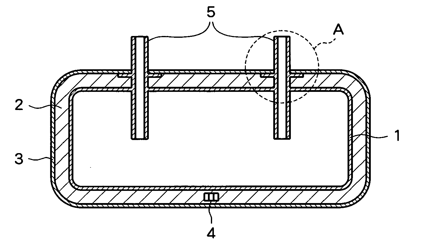
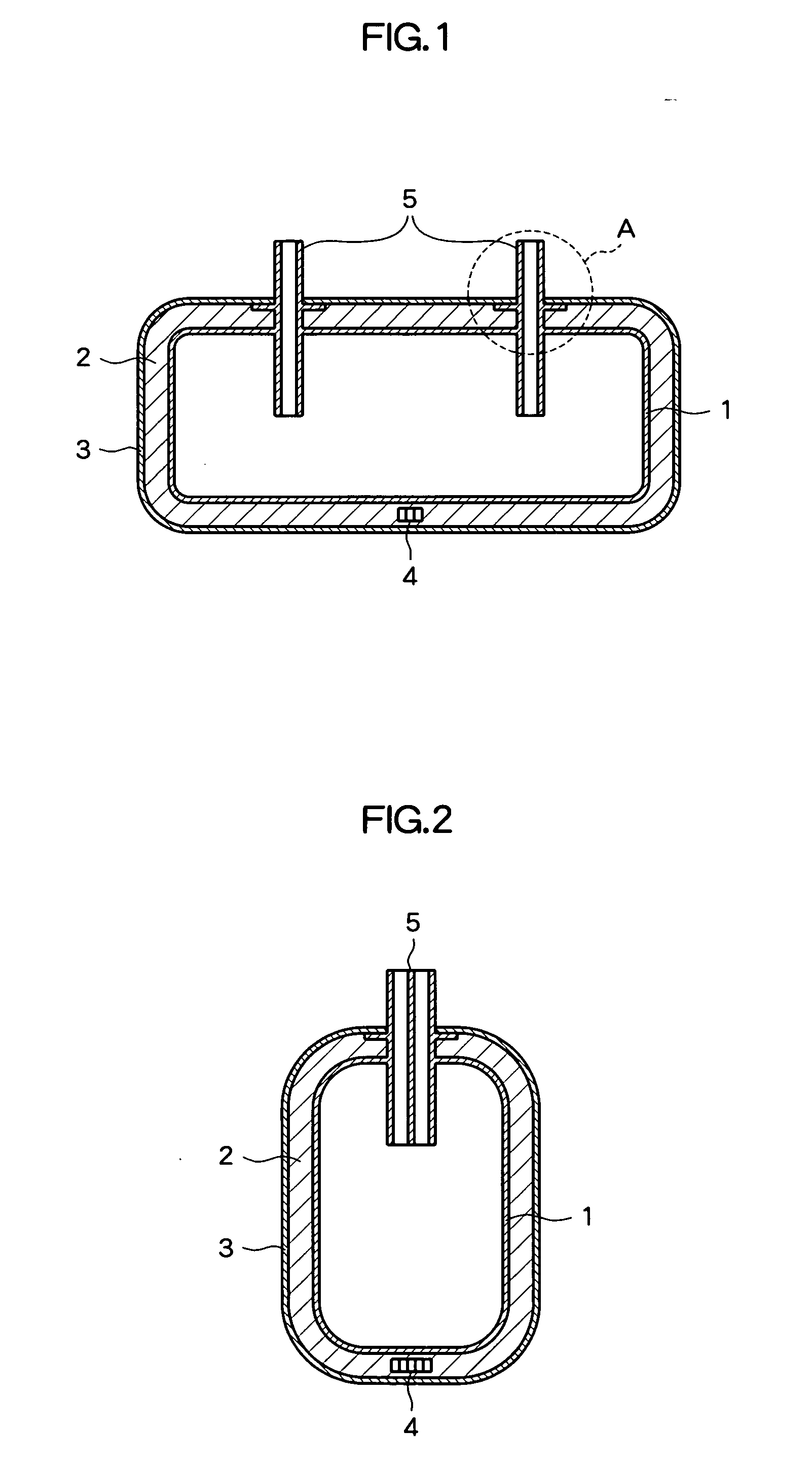
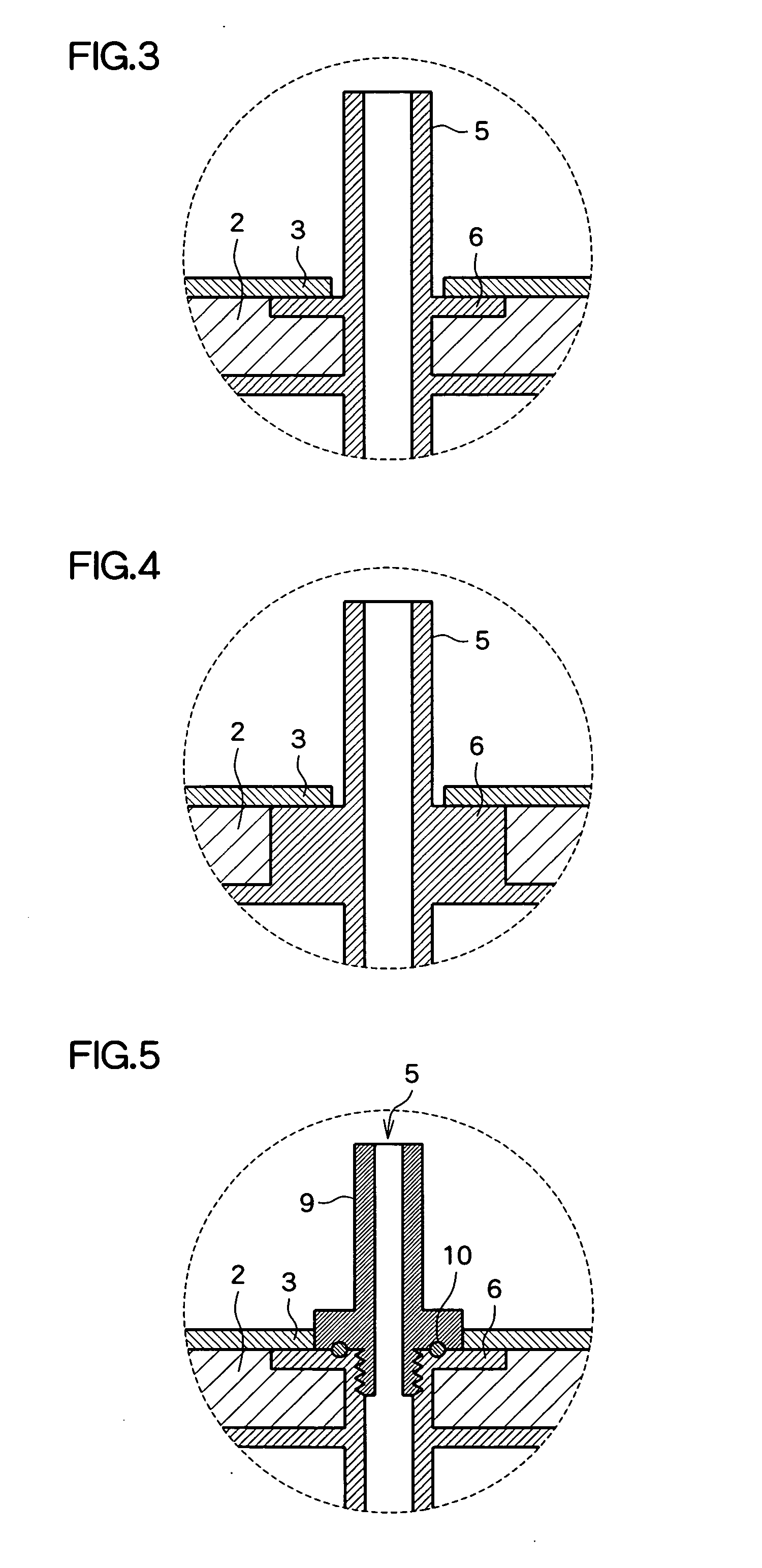
[0058]A rectangular polyethylene container having an internal volume of approximate 2.6 L and a thickness of 8 mm was used as the inside container 1 of the present invention. Liquid inlet and outlet opening part 5 having an external diameter of 18.5 mm, an internal diameter of 13 mm, and a height of 30 mm were formed in one surface of the inside container 1. Flanges 6 having an external diameter of 12 mm and a thickness of 3 mm were formed on the inlet and outlet opening part 5. ABS resin layers were formed on the surfaces of the inside container 1 except at the surfaces of the flanges 6. Next, an electroless nickel plating layer was formed, and an electrolytic copper plating layer was further formed, so that a gas barrier layer was formed.

[0059]A film having a multi-layer structure composed of a polyethylene terephthalat...


PUM

PropertyMeasurementUnit
Temperatureaaaaaaaaaa
Thicknessaaaaaaaaaa
Pressureaaaaaaaaaa

Abstract

The present invention provides a heat-insulating container and a method for manufacturing the same which make it possible to lower manufacturing costs, and to obtain a sufficient heat-insulating effect, and which are also suitably used in a limited installation space such as an engine compartment or the like. The present invention is a heat-insulating container for storing and maintaining a temperature of a liquid, comprising an inside container (1) having inlet and outlet opening part (5) for the liquid, and a sheet-form outer covering (3) which accommodates the inside container (1). A heat-insulating material (2) is sealed between the outer covering (3) and the inside container (1), and a heat-insulating space in a state of reduced pressure is formed between the outer covering (3) and the inside container (1), flange parts are formed on the liquid inlet and outlet openings of the inside container (1), the outer covering (3) and the inside container (1) are joined by the flange parts. The resulting heat-insulating container has exceptional heat-insulating properties and can be used in a limited space.

Description

CROSS-REFERENCE TO RELATED APPLICATION[0001]The priority application number JP2007-079456 upon which this patent application is based is hereby incorporated by the reference.BACKGROUND OF THE INVENTION[0002]1. Field of the Invention[0003]The present invention relates to a heat-insulating container for storing and maintaining the temperature of liquids, and more specifically relates to a heat-insulating container for storing and maintaining the temperature of cooling water used in vehicle engines.[0004]2. Description of the Related Art[0005]Conventionally, heat-accumulating tanks comprising an inner cylinder which stores a liquid, and an outer cylinder which accommodates the inner cylinder therein, wherein a heat-insulating space in a vacuum state is formed between the outer cylinder and the inner cylinder, are known as heat-insulating containers. These containers are necessary in order to store and maintain the temperature of cooling water for use in vehicle engines (long-life coola...

Claims


Application Information

Patent Timeline
IPC IPC(8): B65D81/38B31B49/00A47J41/00B31B50/00
CPCF01P11/029F24H1/182F24H9/12Y10T29/49826Y02E60/142F28F2270/00Y10T29/49F28D20/0034Y02E60/14
Inventor TSUKAHARA, KEIJIOHMURA, TAKAHIROYANO, KUNIHIKO
Owner NICHIAS CORP
Learn More