Method and apparatus for distance measurement

a distance measurement and distance measurement technology, applied in the direction of optical radiation measurement, instruments, using reradiation, etc., can solve the problems of complicated distance measurement apparatus, negative impact of apparatus on the measurement accuracy of distance data, and creation of oscillations, etc., to achieve simple configuration, high measurement accuracy, and low cost

Active Publication Date: 2008-10-02
STANLEY ELECTRIC CO LTD
View PDF3 Cites 55 Cited by
  • Summary
  • Abstract
  • Description
  • Claims
  • Application Information

AI Technical Summary

Benefits of technology

[0014]The presently disclosed subject matter has been devised to consider the above and other problems, features and characteristics. Thus, according to an aspect of the disclosed subject matter, an embodiment of the disclosed subject matter can include a method for measurement distance with high measurement accuracy under various circumstances by adjusting a favorable amount of modulated light emitted from the light source towards an object. The method can have a simple configuration and be realized at low cost. Another embodiment of the disclosed subject matter can include a distance measurement apparatus using or performing the immediately above described method. The distance measurement apparatus can measure a distance of an object and can also generate distance data along with image data using a serial frame data format with a simple configuration and at low cost, and therefore can have practical uses related to a vehicle, a robot, security system, and the like.
[0016]Another aspect of the disclosed subject matter includes a distance measurement apparatus using the above-described method for a distance measurement. The distance measurement apparatus can accurately measure a distance of an object with a simple configuration and at low cost. Thus, the distance measurement apparatus can be incorporated into various sensor systems for measuring a distance of an object(s), the object(s) including an obstacle, a vehicle, an invader and the like for a vehicle, a robot, a security system, etc.
[0024]According to the above-described aspects of the disclosed subject matter, each light intensity of the modulated light rays emitted from each of the plurality of emitting areas can be adjusted to a favorable intensity in accordance with each of the plurality of detecting areas. Thus, the above-described method for distance measurement can measure the distance of an object with higher accuracy under various circumstances and can generate accurate distance data along with the image data using a frame data format. In addition, the method can include prevention from using unnecessary power consumption by controlling a favorable light intensity of the modulated light based on each emitting area.
[0026]In the immediately above-described aspect, the controller can carry out the adjustment and the extraction described in paragraphs [0016]-[0017]. Thus, the distance measurement apparatus using the method described in paragraph [0015] can accurately measure a distance of an object with a simple configuration and at low cost by using a typical controller for a solid state camera.
[0028]In the immediately above-described exemplary embodiment, the controller can carry out each adjustment and each extraction described in paragraphs [0020]-[0021]. Thus, the distance measurement apparatus using the method described in paragraph [0019] can measure a distance of an object with higher accuracy and with a simple configuration by using a typical controller for a solid state camera.

Problems solved by technology

However, when a laser light source is used as a light source in a distance measurement apparatus, a major driver is used to create an oscillation thereof.
Thus, the configuration including the major driver and the adjustor may result in a complicated distance measurement apparatus.
However, according to a distance measurement apparatus using this disclosed conventional method, because an amount of light emitted from the light source is maintained at a constant level, the apparatus may have a negative impact on measurement accuracy of distance data.
For instance, when the modulated light is too dark, because the ratio of the modulated light to a background light decreases, the signal to noise ratio decreases and therefore an error of measurement distance may increase.
On the other hand, when the modulation light of the light source is too bright, because the image sensor is saturated with charges from the incoming light including the reflex light reflected from the object, the distance may not be measured.
In addition, because brightness decreases in inverse proportion to a square of the distance from the light source to an object, when the distance from the light source to an object is relatively near, such as when indoors, and a distance area measured is limited to the distance measurement apparatus, a large error may not be caused even if an amount of light emitted from the light source is maintained constant.

Method used


Image

  • Method and apparatus for distance measurement
  • Method and apparatus for distance measurement
  • Method and apparatus for distance measurement

Examples


first exemplary embodiment

[0045]An example of a distance measurement apparatus in accordance with a first exemplary embodiment of the disclosed subject matter will now be described in detail with reference to FIGS. 1-13.

[0046][Configuration of a Distance Measurement Apparatus]

[0047]A particular configuration of the distance measurement apparatus in accordance with the first exemplary embodiment will now be given.

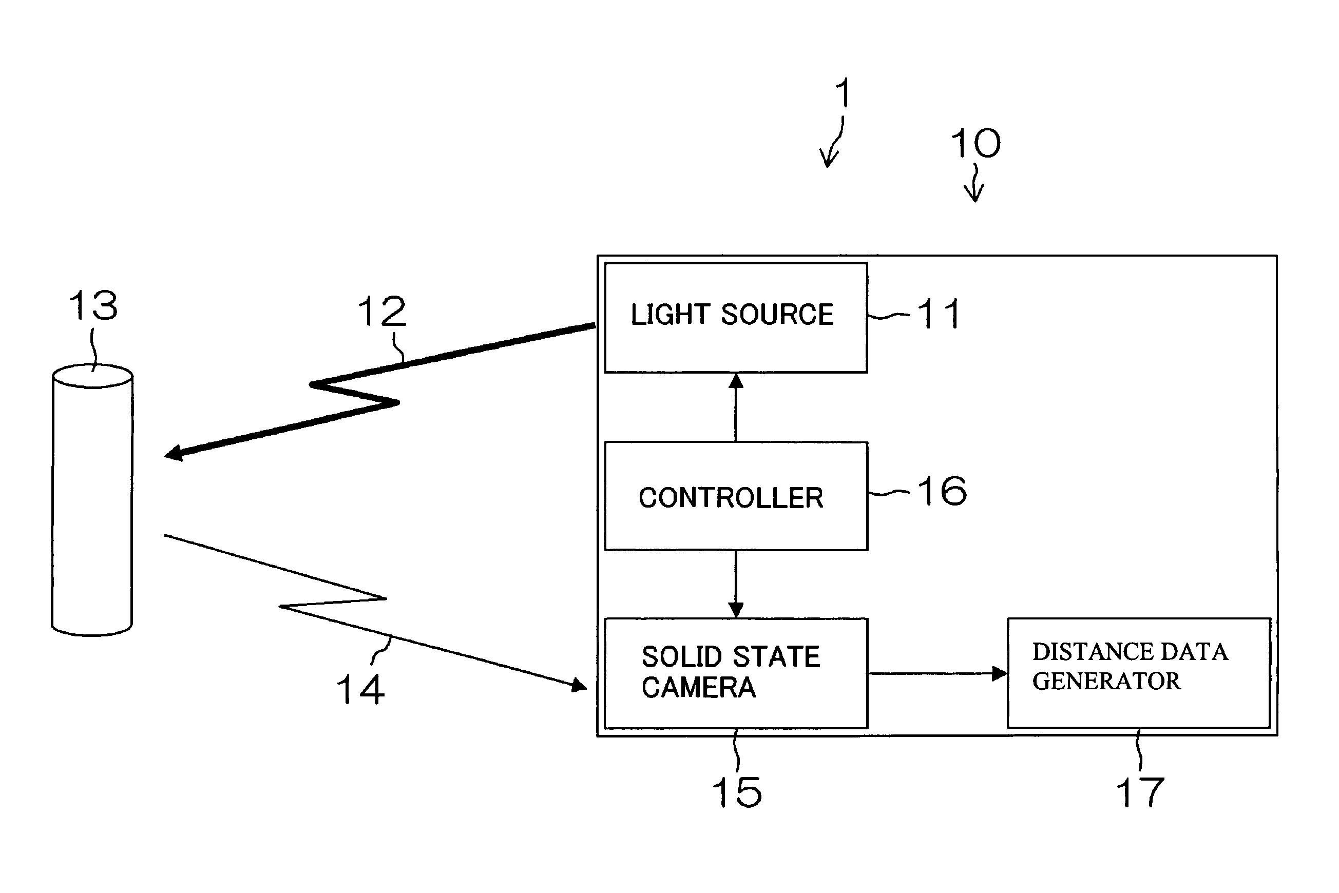
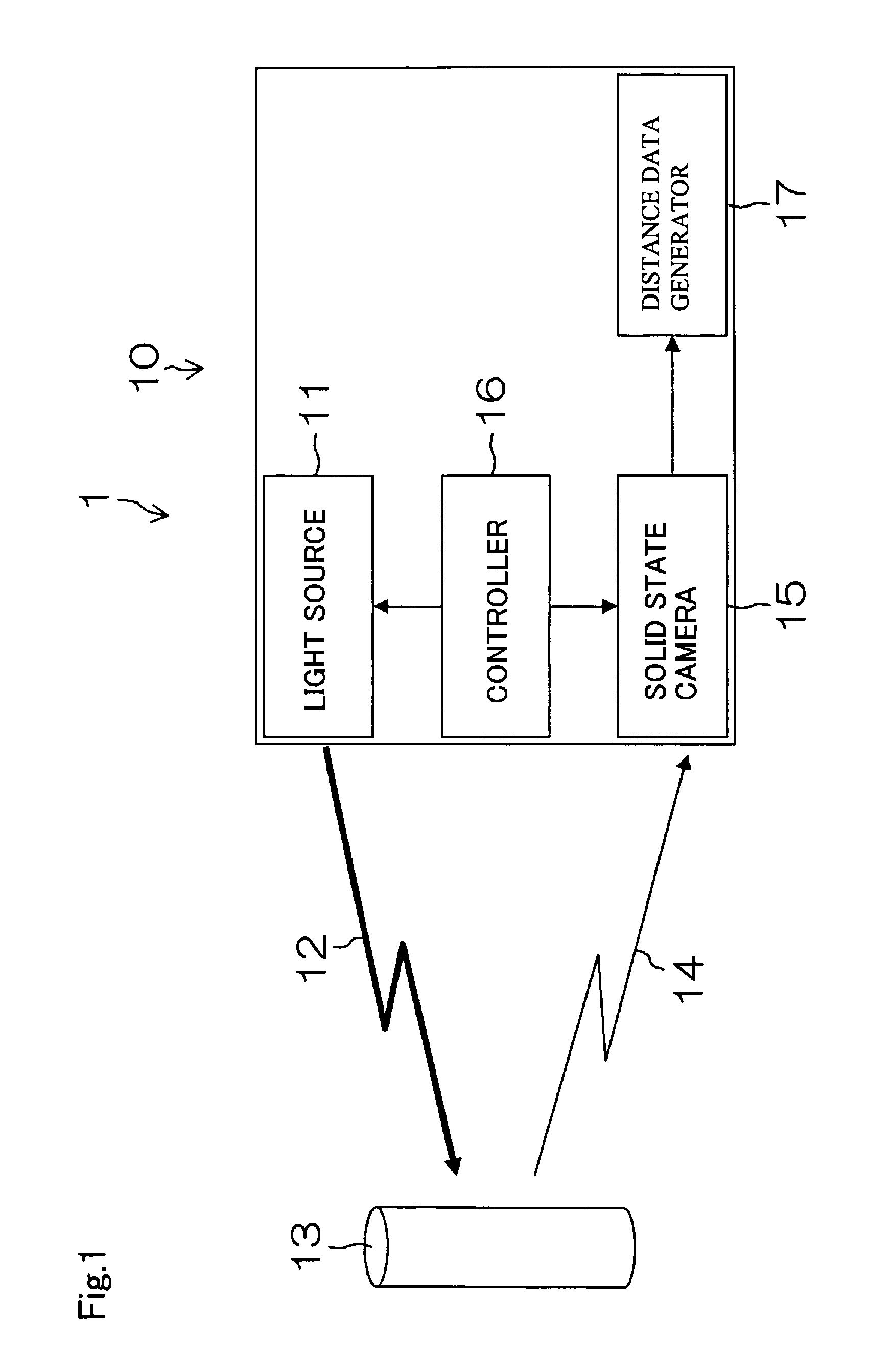
[0048]FIG. 1 is a block diagram of the exemplary distance measurement apparatus made in accordance with principles of the disclosed subject matter. The distance measurement apparatus 1 can be configured to include a distance image sensor 10 using the TOF method as shown in FIG. 1. The distance image sensor 10 can include a light source 11, a solid state camera 15, a controller 16 and a distance data generator 17.

[0049]The light source 11 can be configured to emit a modulated light 12 having a predetermined frequency (e.g. an infrared light or a visible light modulated with high speed using a sine wav...

second exemplary embodiments

[0133]A second example of a distance measurement apparatus made in accordance with principles of the disclosed subject matter will now be described in detail with reference to FIGS. 14-15.

[0134][Configuration of a Distance Measurement Apparatus]

[0135]When measuring a forward distance by the distance measurement apparatus 1 attached to a vehicle, for example attached to a front of the vehicle, the items in the upper portion of the image data are often relatively far away (such as sky, etc.), and items in the lower portion are often positioned relatively near the apparatus 1, such as roadway, a part of the driven vehicle, etc. Thus, the distance measurement apparatus 1 can be configured to change the light intensity of the modulated light emitted from the light source 11 based on each of the various locations of the image data.

[0136]The distance measurement apparatus 1 in accordance with the second exemplary embodiment of the disclosed subject matter can change the light intensity of ...


PUM


Abstract

The disclosed subject matter relates to a method and distance measurement apparatus for measuring a distance to an object, which can include a light source, a solid state camera, a controller and a distance data generator. The light source can be configured to emit a modulated light towards an object, and the solid state camera can convert the light reflected from the object into charges. The distance data generator can be configured to calculate the distance based on the charges, and the controller can be configured to adjust the modulated light to be more favorable under various circumstances. Thus, the method of the disclosed subject matter can accurately measure distance under various circumstances and can result in providing a distance measurement apparatus with a simple configuration and at low cost, and can be used as a sensor for distance measurement of an obstacle and the like in a vehicle, security system, robot, etc.

Description

[0001]This application claims the priority benefit under 35 U.S.C. § 119 of Japanese Patent Application No. 2007-081763 filed on Mar. 27, 2007, which is hereby incorporated in its entirety by reference.BACKGROUND[0002]1. Field[0003]The presently disclosed subject matter relates to a method for distance measurement and a distance measurement apparatus using the method for distance measurement. The distance measurement apparatus and method can be used whenever it is desired to measure a distance of a moving object with high accuracy and under various circumstances by emitting a modulated light towards the moving object. The disclosed subject matter is particularly suitable for use in a vehicle, a robot, security system and the like.[0004]2. Description of the Related Art[0005]A conventional method for distance measurement that can be employed in a vehicle and the like is disclosed, for example, in patent document No. 1 (Japanese Patent Application Laid Open JP2005-182137), patent docu...

Claims


Application Information

Patent Timeline
Patent Type & Authority Applications(United States)
IPC IPC(8): G01J1/32G01S17/32G01S17/89G01S17/931
CPCG01S17/32G01S17/89G01S17/936G01S17/931
Inventor IKENO, RYOHEIKAWATA, TADASHIKUBO, FUMIO
Owner STANLEY ELECTRIC CO LTD
Why Eureka
Try Eureka