High-efficiency, low-debris short-wavelength light sources

Inactive Publication Date: 2008-10-02
HYPERION SCI
View PDF33 Cites 26 Cited by
  • Summary
  • Abstract
  • Description
  • Claims
  • Application Information

AI Technical Summary

Benefits of technology

[0031]The invention has a relatively high conversion efficiency (“CE”, which for a given laser power, is the amount of short-wavelength light that can be collected and used for an application) because it utilizes more of the source material and collects radiation from nearly 4π steradians or at least, more than 2π steradians. In a preferred embodiment of the present invention, the collector optics nearly surround the source material so that the system can take advantage of light emission in nearly 4π steradians. A preferred optics system is generally shaped as an ellipsoid and may include additional reflectors to reduce the number of energy-depleting reflections that are necessary to focus the light toward an end-use tool.
[0032]Utilizing source materials with high 13.5 nm conversion efficiencies relaxes requirements for the average laser power

Problems solved by technology

Heating source material to such high temperatures requires extremely high energy inputs.
Focusing radiated light requires precise and expensive optical systems, as well.
Source material costs can also be extremely high because source material must be delivered continuously to a precise location for being heated by the laser or discharge process.
Prior systems for generating short-wavelength light have not been efficient because, in part, they require radiation substances of high density or inefficient geometries.
To avoid problems associated with overly dense radiating materials, lighter density materials have been considered, but such light density materials may not be heated sufficiently because the laser fails to strike an adequate amount of mass to raise the material's temperature.
Further, heating a source material to such high temperatures results in some

Method used


Image

  • High-efficiency, low-debris short-wavelength light sources
  • High-efficiency, low-debris short-wavelength light sources
  • High-efficiency, low-debris short-wavelength light sources

Examples


Embodiment Construction

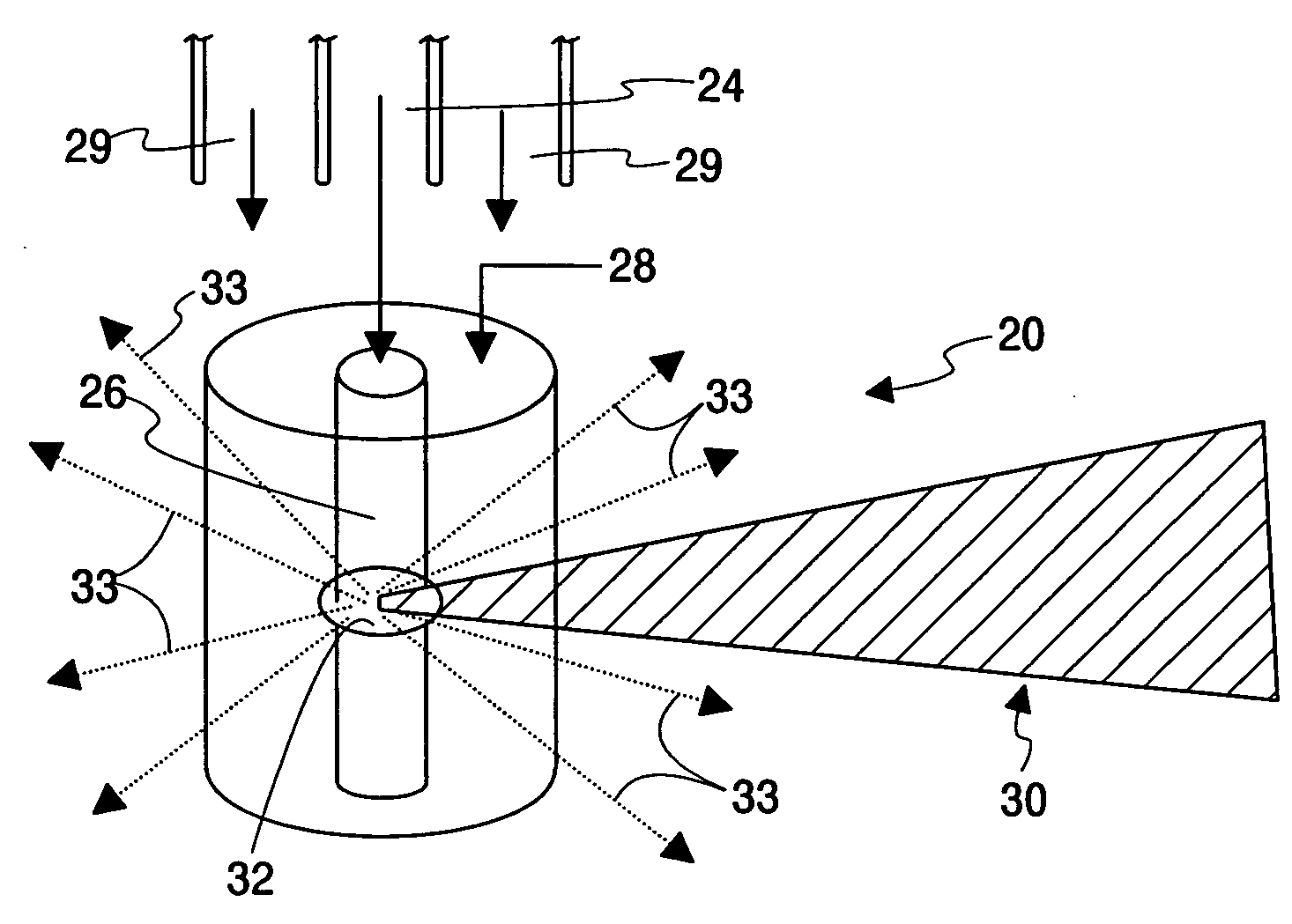
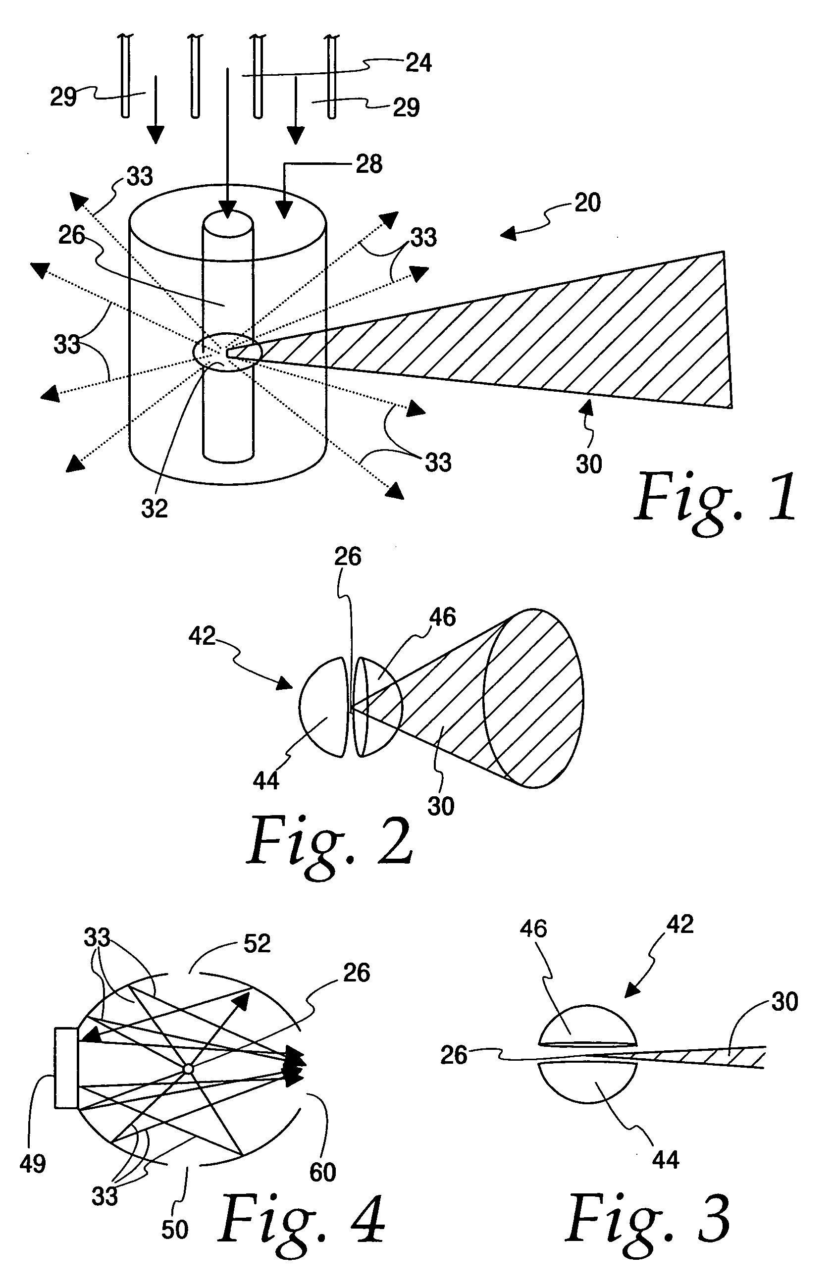
[0042]In the following detailed description of the preferred embodiments, the same reference numeral will be used to identify the same item in each of the drawings. As seen in FIG. 1, a system 20 in accordance with the present invention includes a nozzle 24 emitting a continuous source of radiating source material 26, a gas “cocoon”28 emitted from a nozzle 29, a CO2 laser beam 30 for heating the radiating material 26 to a temperature where it becomes a plasma 32 radiating light 33 in nearly all directions.

[0043]Source materials 26 useful in the present invention are acted upon by laser light 30 or a discharge process or both to radiate short-wavelength light 34. The source material 26 can include a primary radiating material (“hot source material”), and may include a carrier such as a gas of low atomic weight, such as H2 or He, in which the primary radiating material is embedded. The primary radiating material can also be embedded in water droplets. For lithography applications, typ...


PUM


Abstract

This invention relates generally to short-wavelength radiation from laser-produced and discharged produced plasmas, and more particularly to efficient systems and methods for obtaining short-wavelength radiation.

Description

[0001]This application claims priority on Application No. 60 / 897,955 filed Jan. 29, 2007, the disclosure of which is incorporated by reference herein.[0002]The U.S. Government has a paid-up license in this invention and the right in limited circumstances to require the patent owner to license others on reasonable terms as provided for by the terms of Grant No. OII-0610632 awarded by NSF Phase I SBIR Grant.BACKGROUND OF THE INVENTION[0003]This invention relates generally to short-wavelength radiation from laser-produced and discharged produced plasmas, and more particularly to efficient systems and methods for obtaining short-wavelength radiation.[0004]Short-wavelength (including x-ray or extreme ultraviolet) radiation can be used as an exposure light source in lithography, medical research, and other commercial applications. In the lithography application, extreme ultraviolet (“EUV”) radiation at wavelengths near 13.5 nm can be used in manufacturing semiconductors, for example.[0005...

Claims


Application Information

Patent Timeline
IPC IPC(8): G21G4/00
CPCH05G2/003H05G2/008H05G2/005
Inventor MACFARLANE, JOSEPH J.
Owner HYPERION SCI
Why Eureka
Try Eureka