Amoled drive circuit using transient current feedback and active matrix driving method using the same

a technology of active matrix and drive circuit, which is applied in the direction of electric discharge tubes, instruments, computing, etc., can solve the problems of circuits that cannot be operated, difficult to ensure the stability of the feedback loop, and cannot be overcome in practice, and achieve the effect of fast data driving speed

Active Publication Date: 2008-10-02
HIDEEP INC
View PDF2 Cites 50 Cited by
  • Summary
  • Abstract
  • Description
  • Claims
  • Application Information

AI Technical Summary

Benefits of technology

[0034]Accordingly, the present invention has been made keeping in mind the above problems occurring in the prior art, and an object of the present invention is to provide an AMOLED drive circuit using transient current feedback, which detects transient charging current and causes the detected current to be fed back as the charging current of data lines, thus realizing a fast data driving speed in a low current region.
[0035]Another object of the present invention is to provide an active matrix driving method using the AMOLED drive circuit, which divides the data lines of a display panel into two groups, that is, an odd data line group and an even data line group, and alternately performs a data write operation, thus reducing the number of drive channels required by a drive chip.

Problems solved by technology

This causes a problem that cannot be overcome in practice.
In the drive circuit (U.S. Pat. No. 6,433,488) of FIGS. 1 and 2, described above, parasitic capacitance is generated by a data line drive current input terminal and the current comparator, thus there is a problem in that it is difficult to ensure feedback loop stability due to the capacitance.
In particular, the drive circuit of FIG. 2 is a circuit which is impossible to operate.
Furthermore, in the drive circuit, the accuracy of the data drive current is largely limited.
Another problem, in addition to the above-described problems, occurs in that two lines, which are electrically connected to a drive chip, are required to drive a single data line on a display panel (one line forms a drive current path, and the other forms a data line path).
In particular, the OLED elements generally exhibit excessive variation in characteristics as the duration of use thereof increases.
The variation in the characteristics depending on the duration of use thereof may cause a situation in which it is difficult to smoothly operate the drive circuit of FIG. 3.
In the resistors that are made through two processes and using the feature of the material thereof, considerable matching characteristics cannot be acquired, and the matching characteristics cannot be ensured as the resistance values thereof increase.
However, although, in the drive circuit of FIG. 5, the number of pixel circuits is greatly reduced in contrast to the case of FIG. 4, it cannot be expected that conditions necessary to match the resistors of respective data lines will be decreased or greatly improved.

Method used


Image

  • Amoled drive circuit using transient current feedback and active matrix driving method using the same
  • Amoled drive circuit using transient current feedback and active matrix driving method using the same
  • Amoled drive circuit using transient current feedback and active matrix driving method using the same

Examples


Embodiment Construction

[0065]Preferred embodiments of the present invention are described in detail with reference to the accompanying drawings below. However, the embodiments described below are disclosed only for illustrative purposes, and the details of the present invention are not limited to the embodiment described below.

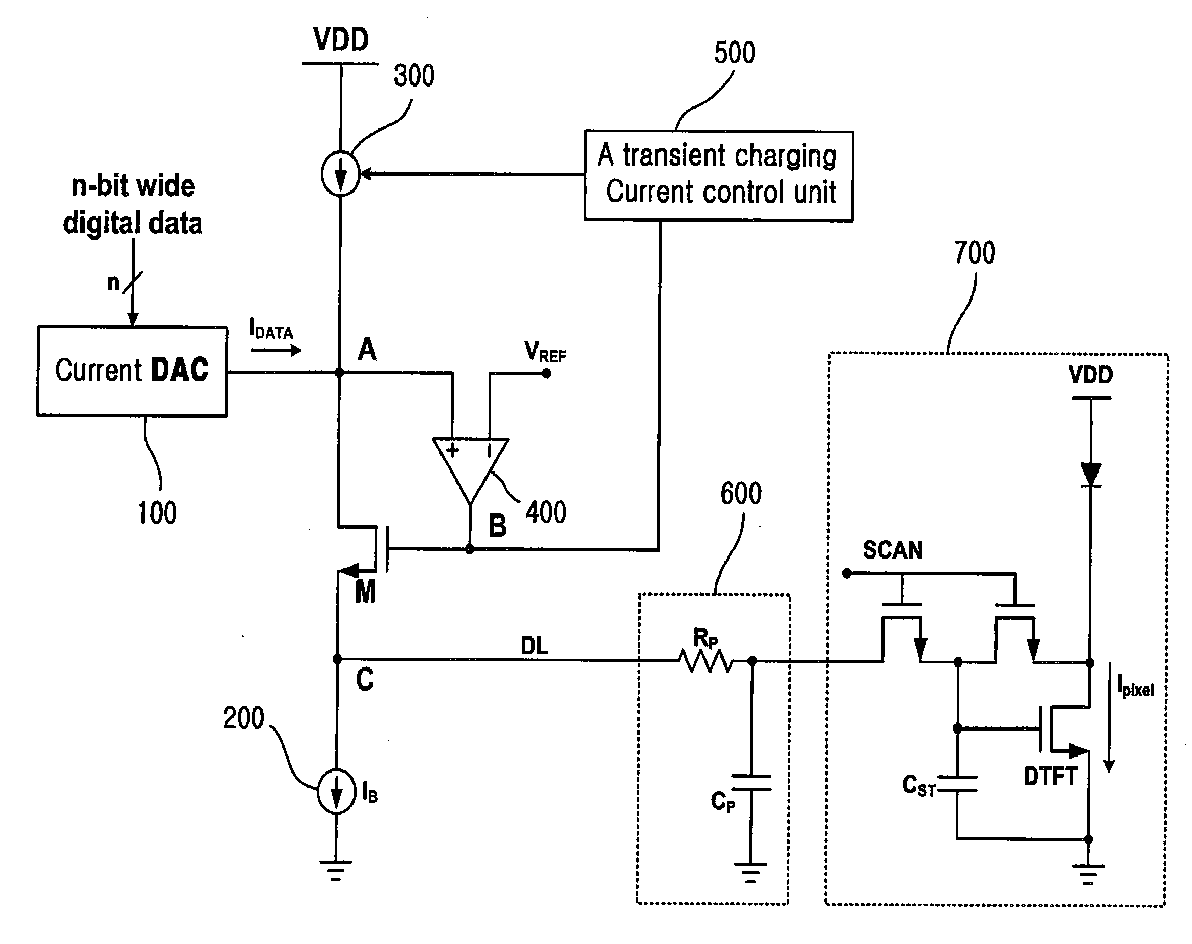
[0066]FIG. 7 is a circuit diagram showing an AMOLED drive circuit using transient current feedback according to the present invention.

[0067]As shown in FIG. 7, the circuit for driving an active matrix display includes a current DAC 100 for receiving n-bit digital data and generating current corresponding to the digital data, a drive transistor M configured such that the drain terminal thereof is connected to the output node A of the current DAC 100 and the source terminal thereof is connected to a data line DL, a constant current source 200 connected between the source terminal of the drive transistor M and a ground, a variable current source 300 configured such that one end thereof...


PUM


Abstract

Disclosed herein is an Active Matrix Organic Light-Emitting-Diode (AMOLED) drive circuit using transient current feedback. The AMOLED drive circuit includes a current Digital-to-Analog Converter (DAC), a data line drive transistor, a constant current source, a variable current source, a differential amplifier, and a transient charging current control unit. The DAC generates current corresponding to input digital data. The data line drive transistor is configured such that the drain terminal thereof is connected to the output node of the current DAC. The constant current source is connected between the source terminal of the data line drive transistor and a ground. The variable current source is connected between both the output node of the current DAC and the drain terminal of the drive transistor, and a voltage source. The differential amplifier is configured to input the output voltage thereof to the gate terminal of the drive transistor. The transient charging current control unit is configured to increase or decrease the bias current of the variable current source depending on variation in the voltage of the output node of the current DAC.

Description

BACKGROUND OF THE INVENTION[0001]1. Field of the Invention[0002]The present invention relates generally to a drive circuit for a flat panel display device and a driving method using the drive circuit and, more particularly, to an Active Matrix Organic Light-Emitting Diode (AMOLED) drive circuit using transient current feedback and an active matrix driving method using the AMOLD drive circuit, which, when an AMOLED display device is driven in a current mode, can overcome a decrease in driving speed, which is caused by charging or discharging due to the parasitic capacitance of data lines, using current feedback based on the detection of transient charging current, and which divide the data lines of a display panel into even data lines and odd data lines and alternately perform a data write operation on the even data lines and the odd data lines, thus reducing the number of channels of a drive Integrated Circuit (IC).[0003]2. Description of the Related Art[0004]An Organic Electrolumin...

Claims


Application Information

Patent Timeline
Patent Type & Authority Applications(United States)
IPC IPC(8): G09G3/12
CPCG09G3/3241G09G3/3283G09G2300/043G09G2310/0248G09G2320/0223G09G2320/0252
Inventor CHO, GYU-HYEONGSON, YOUNG-SUKKIM, SANG-KYUNGJEON, JIN-YONGLEE, GUN-HO
Owner HIDEEP INC
Why Eureka
Try Eureka