
Method and circuit for controlling motor and brushless motor system using the same

Active Publication Date: 2008-10-02
PROLIFIC TECH INC
View PDF17 Cites 28 Cited by
  • Summary
  • Abstract
  • Description
  • Claims
  • Application Information

AI Technical Summary

Benefits of technology

[0023]Accordingly, the present invention is directed to provide a method for controlling a motor, a circuit for controlling a motor and a brushless motor system using the method or employing the circuit. The present invention is able to detect zero-crossing points of motor in a PWM-on state further to control the commutation of the motor and furthermore, as shown by the preferred embodiment of the present invention, to reduce commutation error in association with detecting zero-crossing points of motor in a PWM-on state.
[0035]Since the present invention adopts a scheme that when there is a current flowing from the second terminal of the second specific coil among the above-mentioned three-phase coils to the second terminal of the specific third and there is no current flowing through the first specific coil, the voltage at the second terminal of the first coil is detected and the detected voltage is defined as a first specific voltage, the voltage drop across a DC sensing resistor is detected and the detected voltage drop is defined as a second specific voltage, following by using the first specific voltage, the second specific voltage and the DC voltage supplied to the motor to estimate zero-crossing points to control the motor, therefore, there is no need of a filter of the prior art and no phase delay problem during detecting zero-crossing points with the present invention. In addition, the circuit provided by the embodiment of the present invention allows detecting zero-crossing points by detecting the non-excited stator coils whenever in a PWM-on state or in a PWM-off state.

Problems solved by technology

However, the above-mentioned brushed motor has many drawbacks, it is cumbersome, accompanied by noise during working and inefficient.
In some circumstances or application structures however, a motor does not allow disposing Hall sensors; for example, the compressor motor of a cooler or a refrigerator is a closed motor, which is required to operate at quite high temperatures.
However, it is noted that the scheme by using a voltage-dividing circuit would decay the captured signal.
On the other hand, a phase delay of the filter is varied with the motor speed, which makes the detection of a zero-crossing point inaccurate and results in thereby a commutation error of the motor.
Referring to FIG. 4, in the patent [1], a clamping circuit 40 coupled to the nodes A, B and C of the stator coils of a motor is used to estimate the voltage at the node B when a current flows from A to C and an upper bridge switch S401 is cut off, the drawback of the method is that a minimum switch closing time is definitely required which limits the application of the method.
A compensation of a constant voltage proposed by [2] would cause a commutation phase error.
The method by modifying the current flowing paths, however, is not suitable for common applications.
However, the method is unable to suit a motor having large speed variations or an asymmetrical motor.
If a real zero-crossing point fails to be measured by using the above-mentioned schemes of the patents [8, 9], the motor may stop down immediately due to no available commutation, which causes a reverse surge current, burns the pre-stage circuit and puts the motor and the applied system in danger.
However, there is no standard to define the longest time and the shortest time; thus, the simplest way to utilize the method provided by the patent [10] is to measure various delay time of commutation in respond to different operation speeds and store the measured time information in the above-mentioned storage unit, which results in cost-wasting a lot.[01] J. M. Bourgeois, J. M. Charreton, P. Guillemin, and B. Maurice, “Control of a brushless motor,” U.S. Pat. No. 5,859,520, STM, Jan. 12, 1999.[02] J. Shao, D. C. Nolan, K. A. Haughton, and T. L. Hopkins, “Circuit for improved back EMF detection,” U.S. Pat. No. 6,633,145, STM, Oct. 14, 2003.[03] E. C. Lee, “BEMF crossing detection in PWM mode operation for sensorless motor control application,” U.S. Pat. No. 5,789,895, STM, Aug. 4, 1998.[04] R. Sakti and K. K. Chow, “BEMF zero-crossing detection system of a multiple-phase motor,” U.S. Pat. No. 5,909,095, STM, Jun. 1, 1999.[05] P. Menegoli, “Circuit for improving back-EMF detection in pulse-width modulation mode,” U.S. Pat. No. 5,866,998, STM, Feb. 2, 1999.[06] G. Maiocchi and M. Viti, “Reconstruction of BEMF signals for synchronizing the driving of brushless sensorless motors by means of predefined driving signals,” U.S. Pat. No. 5,838,128, STM, Nov. 17, 1998.[07] S. W. Cameron, “Method and apparatus for resynchronizing a moving rotor of a polyphase DC motor,” U.S. Pat. No. 5,172,036, STM, Dec. 15, 1992.[08] W. S. Gontowski, “Sensorless motor driver with BEMF mask extender,” U.S. Pat. No. 6,504,328, STM, Jan. 7, 2003.

Method used


Image

  • Method and circuit for controlling motor and brushless motor system using the same
  • Method and circuit for controlling motor and brushless motor system using the same
  • Method and circuit for controlling motor and brushless motor system using the same

Examples


Embodiment Construction

[0057]Reference will now be made in detail to the present preferred embodiments of the invention, examples of which are illustrated in the accompanying drawings. Wherever possible, the same reference numbers are used in the drawings and the description to refer to the same or like parts.

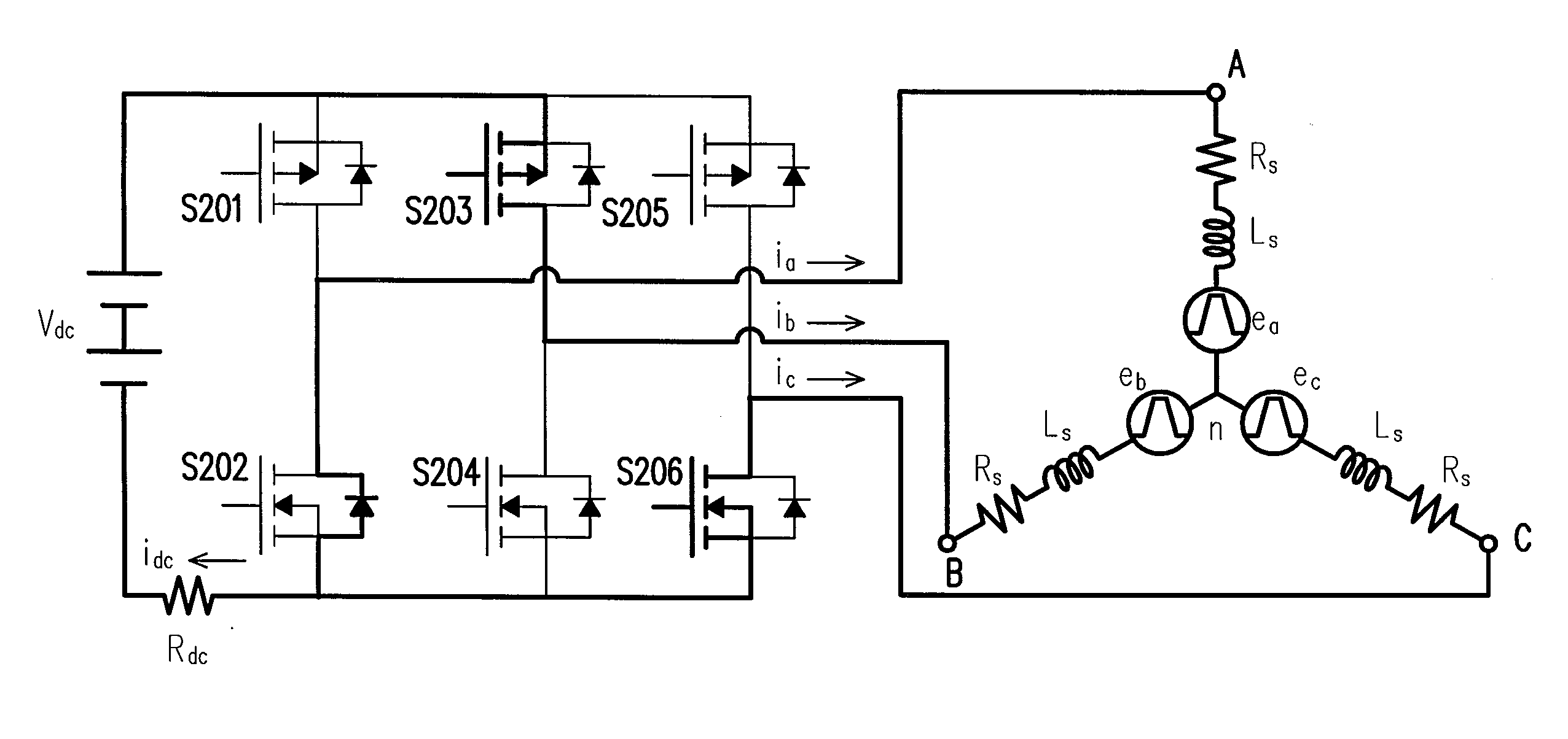
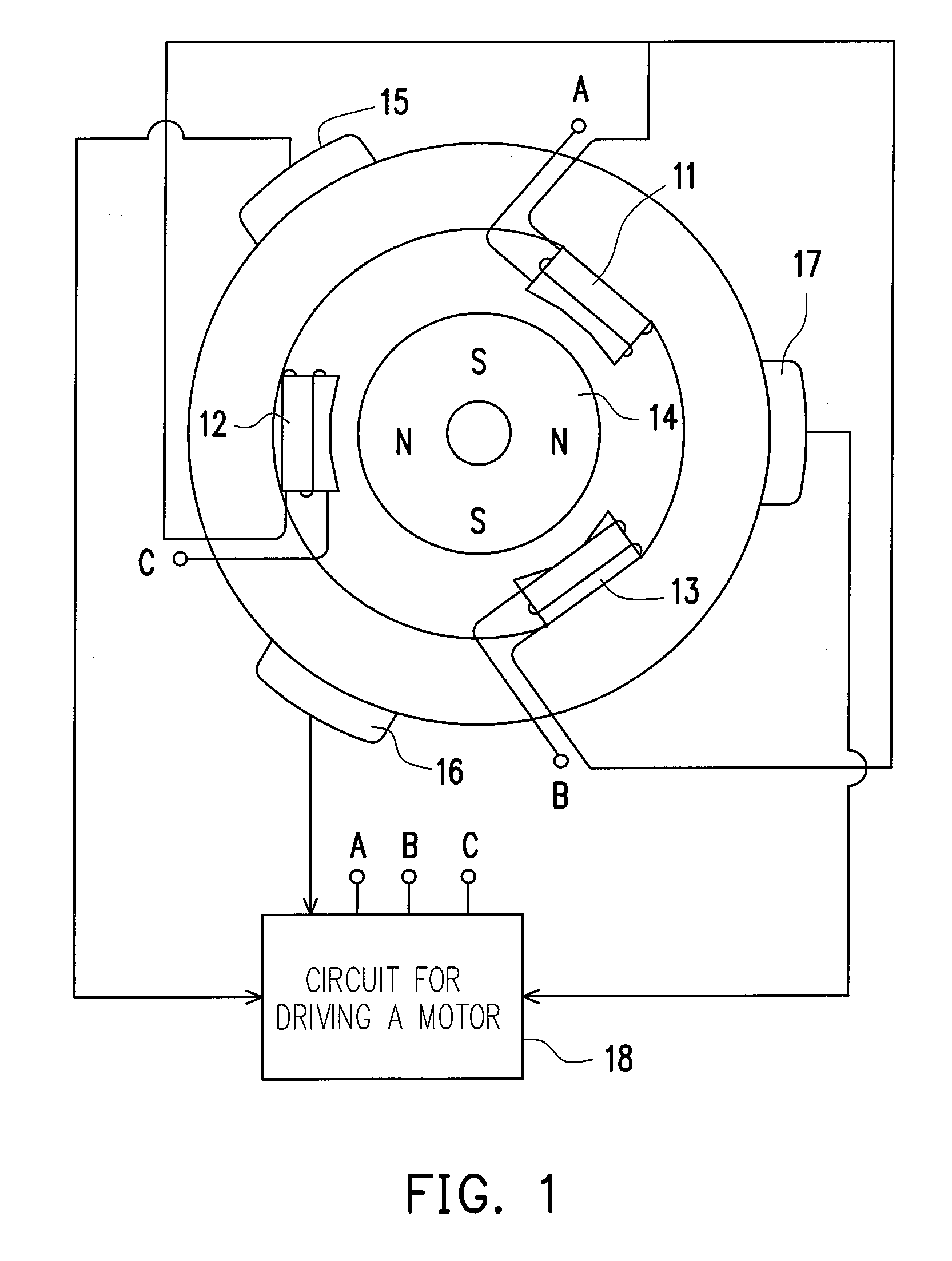
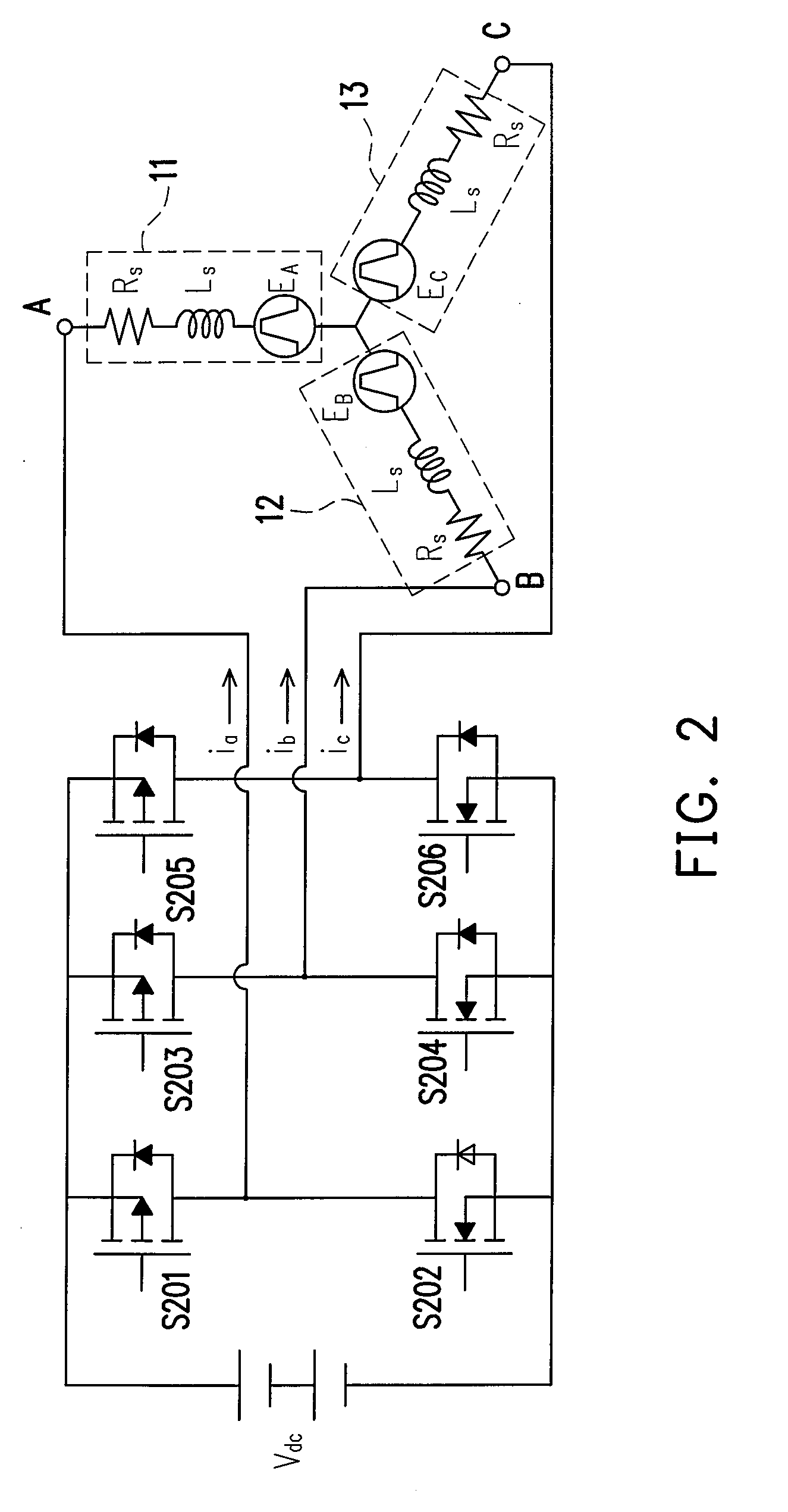
[0058]In order to solve the problem with the prior art, a method for detecting rotor positions, a circuit for controlling a motor and a brushless motor system are provided in the present invention. A brief analysis on a back-EMF which is closely related to a motor position is introduced prior to the depiction of the method and the apparatus. In the following, a three-phase motor shown by FIG. 2 and a brief mathematic / circuit analysis thereof are exemplarily explained.

[0059]Assuming the equivalent resistor in series connection RS of each stator coil 11, 12 or 13 is a constant value and the equivalent inductance LS of every stator coil is equal to each other, thus, the voltages at nodes A, B and C of t...


PUM


Abstract

A method and a circuit for controlling a motor and a brushless motor using the same are provided. The brushless motor includes three phase coils, wherein the first terminals of all the phase coils are coupled to a common node. The method includes following steps: among the above-mentioned three phase coils, when there is no current flowing through the first phase coil of the above-mentioned three phase coils and a current flows from the second terminal of the second coil to the second terminal of the third phase coil, detecting the voltage at the second terminal of the first phase coil to be a first specific voltage; detecting the voltage drop of a DC sensing resistor to be a second specific voltage; and utilizing the first specific voltage, the second specific voltage and the DC voltage supplied to the motor to estimate zero crossing points for controlling the motor.

Description

CROSS-REFERENCE TO RELATED APPLICATION[0001]This application claims the priority benefit of Taiwan application serial no. 96105234, filed Feb. 13, 2007. All disclosure of the Taiwan application is incorporated herein by reference.BACKGROUND OF THE INVENTION[0002]1. Field of the Invention[0003]The present invention generally relates to a technique for controlling a motor, and more particularly, to a method for controlling a motor, a circuit for controlling a motor and a brushless motor system using the method or employing the circuit.[0004]2. Description of Related Art[0005]A variable speed motor has been broadly used in many applications, such as a factory automation system, a ventilating system, an air conditioning system and the like. A conventional variable speed motor is a brushed motor, on which a set of brushes and a commutator are disposed. Over the past century, graphite brushes and a slip ring (commutator) which the graphite brushes come to contact with have been used to ac...

Claims


Application Information

Patent Timeline
IPC IPC(8): H02P6/08H02P7/06H02P6/18
CPCH02P6/16H02P6/182
Inventor CHENG, KUANG-YAO
Owner PROLIFIC TECH INC
Features
  • Generate Ideas
  • Intellectual Property
  • Life Sciences
  • Materials
  • Tech Scout
  • Unparalleled Data Quality
  • Higher Quality Content
  • 60% Fewer Hallucinations
Learn More