
Mitigation of Interference and Crosstalk in Communications Systems

a technology of communications system and interference, applied in the field of communication system interference and crosstalk mitigation, can solve the problems of shortening the signal clarity is short, and certain limitations of the communication system, so as to shorten the distance at which the signal can be reliably received

Inactive Publication Date: 2008-10-02
TOKYO ELECTRON LTD
View PDF9 Cites 35 Cited by
  • Summary
  • Abstract
  • Description
  • Claims
  • Application Information

AI Technical Summary

Benefits of technology

[0031]Specifically, a noise pre-whitening matrix is combined with a triangular matrix Decision Feedback Demodulator (DFD) at the receiver to extract signals at a performance level similar to that accomplished in the prior art, without requiring delivery of receiver parameters to the transmitter.
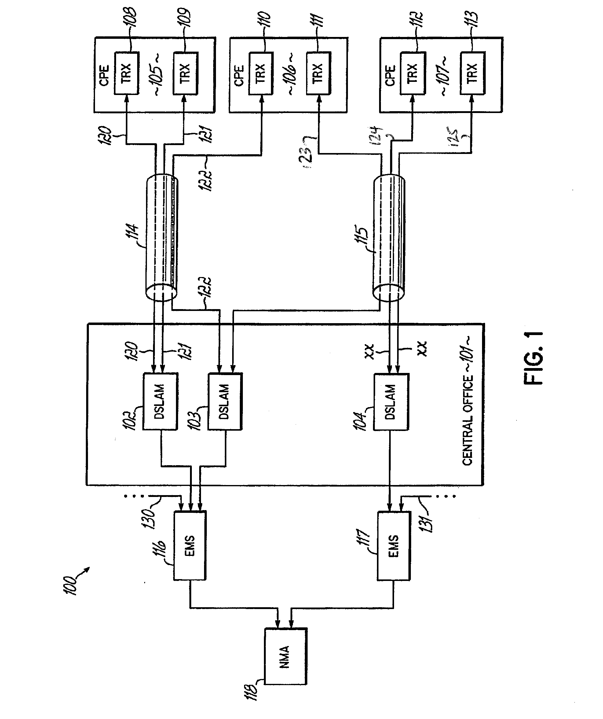
[0034]In another aspect, the invention features a data communication appliance which transfers communications data over a plurality of twisted copper pairs, such as are frequently available at business buildings or private homes which are wired for multiple telephone lines. A multiline processor connected to the twisted copper pairs extracts multiple different channels from the plural twisted pair signal paths, such as voice, POTS, video, video broadcast, pay-per-view video, and internet data. The use of dual twisted pair signal paths permit wideband service from, e.g. incumbent local exchange carriers, permitting effective competition with cable television providers.

Problems solved by technology

Interference in a signal may lead to certain limitations of a communication system.
For example in wireless systems, such as cellular phones, interference may shorten the distance at which the signal can be reliably received and the clarity of the signal.
As another example, in wireline systems, such as digital subscriber lines (DSL), interference may shorten the distance at which the signal can be reliably received, i.e., limit loop reach.
This task, however, is complicated significantly by several factors.
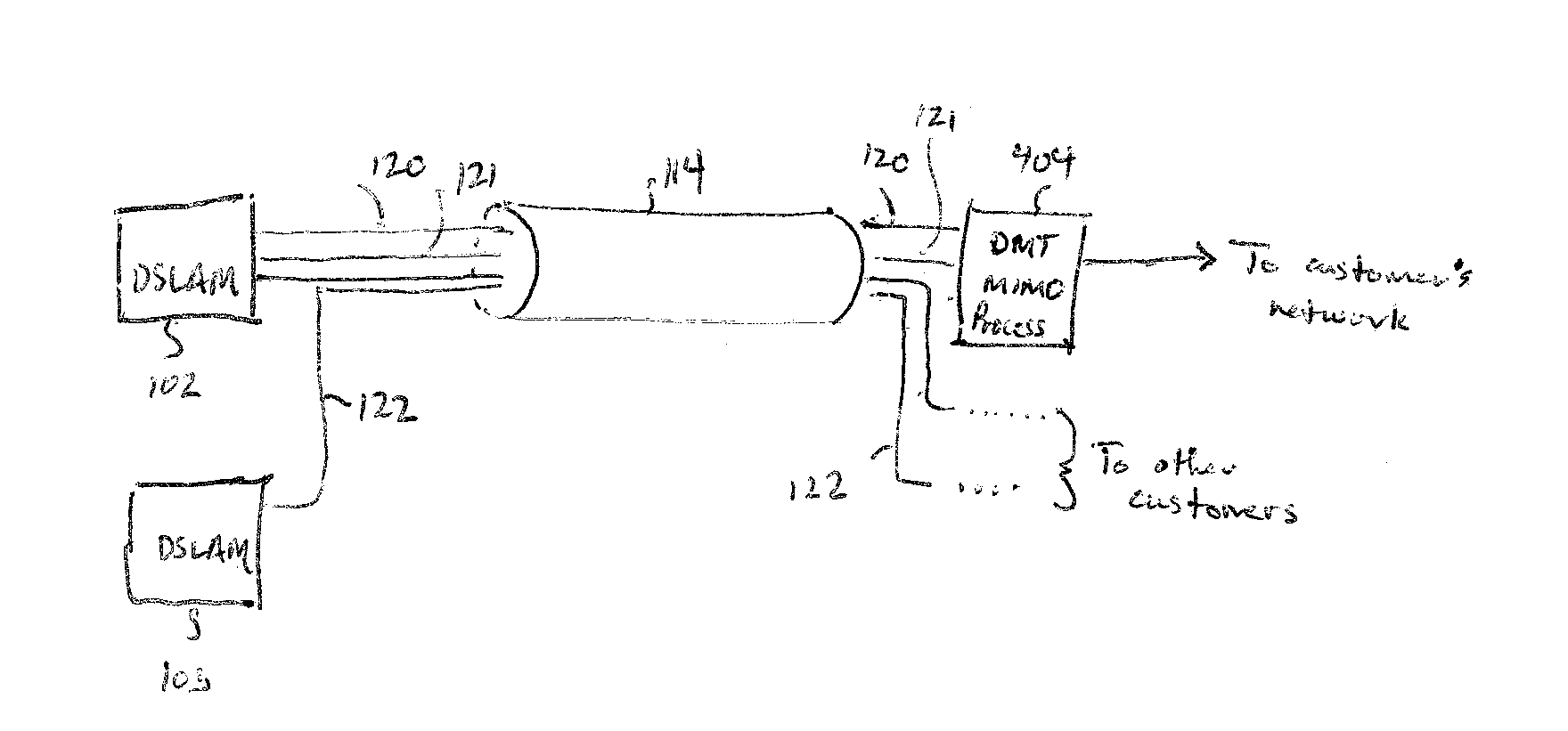
As a result, when used for high-frequency data transmission, these twisted pairs are not adequately protected from receiving high-frequency electromagnetic interference associated with the waveforms that appear on another line; nor are the waveforms on a line prevented from radiating so as to interfere with the waveforms that appear on another line.
When the ordinary telephone lines were originally installed to carry POTS voice traffic, crosstalk was insubstantial because of the lower frequencies used to transmit voice traffic.
However, as DSL is designed to provide higher speed services (as compared to traditional telephony service) over these ordinary telephone lines, DSL waveforms contain much higher frequencies, at which the twisting of the wires does not provide adequate protection.
As a result, crosstalk from DSL waveforms is much more severe.
The more severe crosstalk frequently hampers the successful deployment of a DSL service.
The only way to substantially reduce this crosstalk is to replace the billions of existing copper pairs with shielded copper pairs, or other media such as optical fiber, which may not be economically feasible in many environments.
The principle is the same as that used for echo cancellation in single-line transceivers, but in this case it involves additional complexities associated with a full matrix of crosstalk cancellation filters.
The mitigation of Alien interference, which includes Alien crosstalk from out-of-domain transmitters, and also noise from non-DSL signal sources, is more challenging, since the in-domain receivers do not have access to the signals of the interfering out-of-domain transmitters or non-DSL signal sources.
Without it, Self-NEXT cancellation is of limited benefit, since there is no guarantee that the in-domain component of the interference will be stronger than the out-of-domain or non-DSL component.
A disadvantage of using MIMO techniques on both transmitter and receiver is the need to establish special communication methods between the transmitter and receiver so that the MIMO processing at transmitter and receiver may be coordinated as the channel interference is modeled and managed.

Method used


Image

  • Mitigation of Interference and Crosstalk in Communications Systems
  • Mitigation of Interference and Crosstalk in Communications Systems
  • Mitigation of Interference and Crosstalk in Communications Systems

Examples


Embodiment Construction

[0043]For purposes of discussing and illustrating the invention, several examples of the invention will now be given in the context of a wireline communication system, such as xDSL. However, one skilled in the art will recognize and appreciate that interference, for example, crosstalk, is a problem in wired and wireless communications and that the techniques disclosed are applicable in these areas as well.

[0044]In the following description, for purposes of explanation, numerous specific details are set forth in order to provide a thorough understanding of the present invention. It will be evident, however, to one skilled in the art that the present invention may be practiced without these specific details. In some instances, well-known structures and devices are shown in block diagram form, rather than in detail, in order to avoid obscuring the present invention. These embodiments are described in sufficient detail to enable those skilled in the art to practice the invention, and it...


PUM


Abstract

Signals in a multi-channel, impaired communication system are post-processed at the receiver. A triangular matrix Decision Feedback Demodulator (DFD) at the receiver extracts channels without requiring delivery of receiver parameters to the transmitter. Multi-Input Multi-Output (MIMO) processing matrices and DFD parameters are computed by first applying matrix transformations to diagonalize the noise covariance matrix of the multiple channels received at the receiver. QR decompositions (i.e., decompositions into orthogonal and triangular matrices) are then applied to the main channels to obtain triangular channel matrices. The noise-diagonalizing transformations and QR decompositions are then combined to form the MIMO postprocessing matrices and DFD parameters. MIMO postprocessing matrices and DFD parameters are computed from training data and then adapted during live data transmission.

Description

BACKGROUND OF THE INVENTION[0001]The present invention relates to reducing the effects of interference from crosstalk and other noise sources that interfere with signals transmitted over wires, cable, fiber optics, wireless, or other types of communication where the signals suffer from some level of interference.[0002]Interference generally is generated by signals from other signal sources. For example in Digital Subscriber Line (DSL) systems, interference may originate from other DSL services, in which case it is referred to as crosstalk, or from non-DSL sources such as AM radio transmitters, electrical appliances, and power supplies. Interference does not include unstructured background noise, such as thermal and environmental noise.[0003]Interference in a signal may lead to certain limitations of a communication system. For example in wireless systems, such as cellular phones, interference may shorten the distance at which the signal can be reliably received and the clarity of th...

Claims


Application Information

Patent Timeline
IPC IPC(8): H04J1/12H04M3/34
CPCH04L25/0246H04L25/03006H04L2025/03426
Inventor ERICKSON, MARK ALANGUDMUNDSSON, THORKELLKANELLAKOPOULOS, IOANNISHENCH, JOHN JOSEF
Owner TOKYO ELECTRON LTD
Learn More