Plasma actuated electronic catalytic converter

a technology of electronic catalytic converter and actuation mechanism, which is applied in the direction of mechanical equipment, machines/engines, exhaust treatment, etc., can solve the problems of increasing the back-pressure of the exhaust pipe, serious degrading performance, and a plethora of exhaust after-treatment systems devoted to reducing air pollution

Inactive Publication Date: 2008-10-02
JAYNE MICHAEL E +1
View PDF2 Cites 8 Cited by
  • Summary
  • Abstract
  • Description
  • Claims
  • Application Information

AI Technical Summary

Benefits of technology

[0071]With the enormous personal heartbreak, societal costs, diverted economic resources, and specifically governmental expenditures in the form of Medi-Care and Medic-Aid costs that threaten to bankrupt our healthcare system, there is enormous pressure to get all of the diesel powered vehicles in the USA to pollute much less. With the present invention, it is not necessary to “grandfather” in older vehicles already

Problems solved by technology

The plethora of exhaust after-treatment systems devoted to reduction of pollution of the air are simply too numerous to specifically reference individually.
The reason for this is that to date no practical solution has been found for the following issues:1. High soot (hydrocarbon particulate) output during engine warm-up that leads to clogging of conventional metallic catalyst type catalytic converters;2. Very high NOx output due to the nature of compression ignition used by diesel engines; and3. The sensitivity of the diesel engine to any exhaust restriction leading to increased exhaust back-pressure which seriously degrades performance.
These systems have shown enough promise to continue to attract research funding, but they have yet to reach commercial viability.
The reasons for this system's difficulty in development are:1. limitations in handling high amounts of hydrocarbon particulates;2. susceptibility to vibration of the material used to provide a surface area for the corona discharge; and3. the bulk of the apparatus necessary to create enough surface area to treat typical exhaust flow rates.
Although this technology has shown some promise in the laboratory, the above mentioned problems have yet to be given cost effective and market acceptable solutions.
These systems have been under development for a number of years without reaching the market for the following reasons:1. they require either extra fuel or a totally separate tank of its own special fuel to operate;2. the accompanying plumbing and apparatus is complex and expensive; and3. in many cases there is a filter trap that accumulates solid waste that must be disposed

Method used


Image

  • Plasma actuated electronic catalytic converter
  • Plasma actuated electronic catalytic converter
  • Plasma actuated electronic catalytic converter

Examples


Embodiment Construction

[0082]The invention will now be described in further detail in connection with illustrative preferred embodiments for improving exhaust after-treatment of industrial processes, furnaces, and internal combustion engines. Special attention will be paid to the problems faced in the treatment of exhaust from diesel engines. There will be presented several different variations of each section of the device within the scope of the present invention.

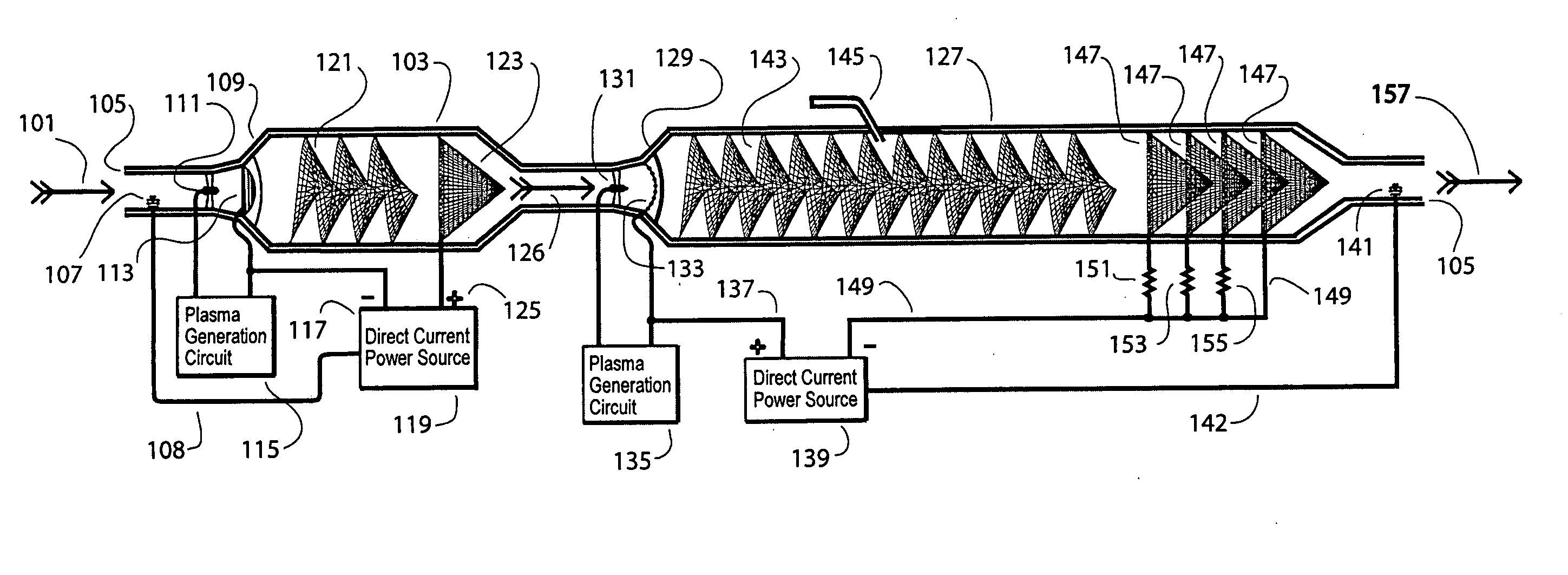
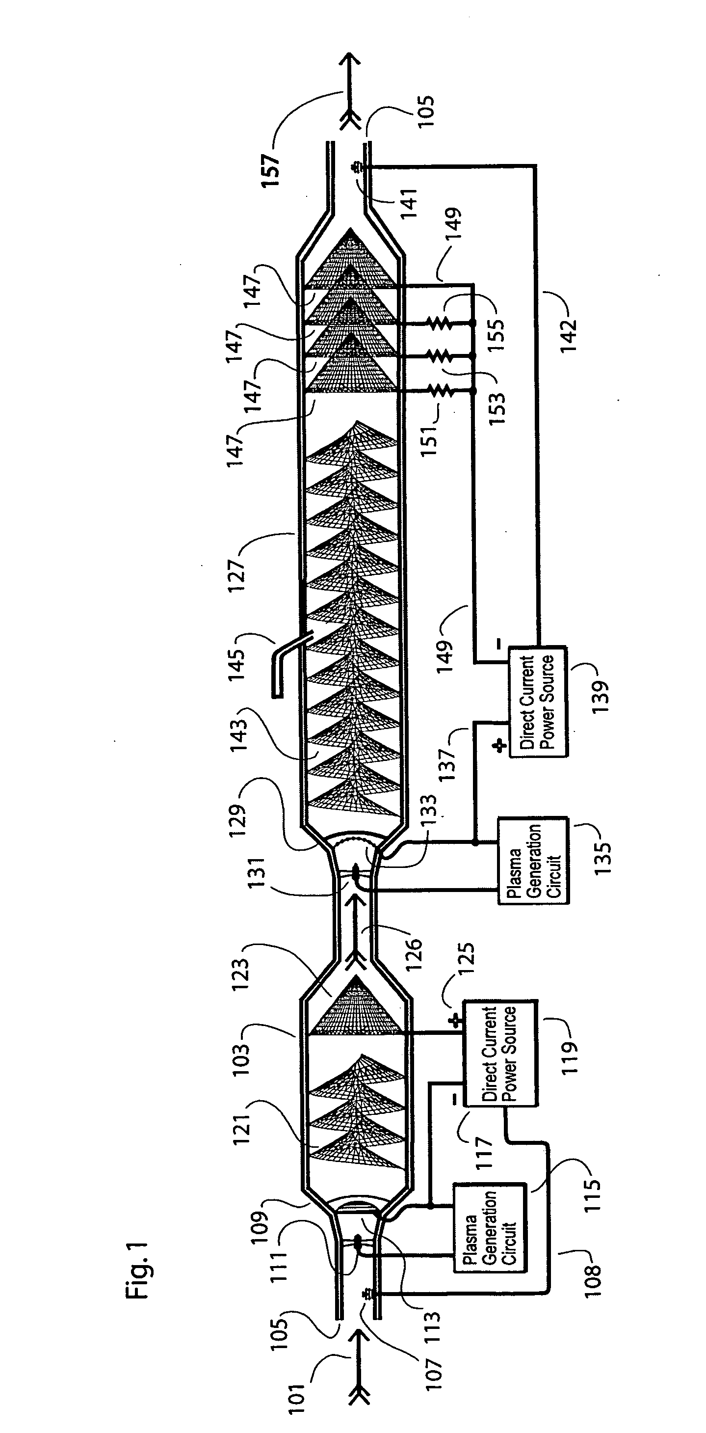
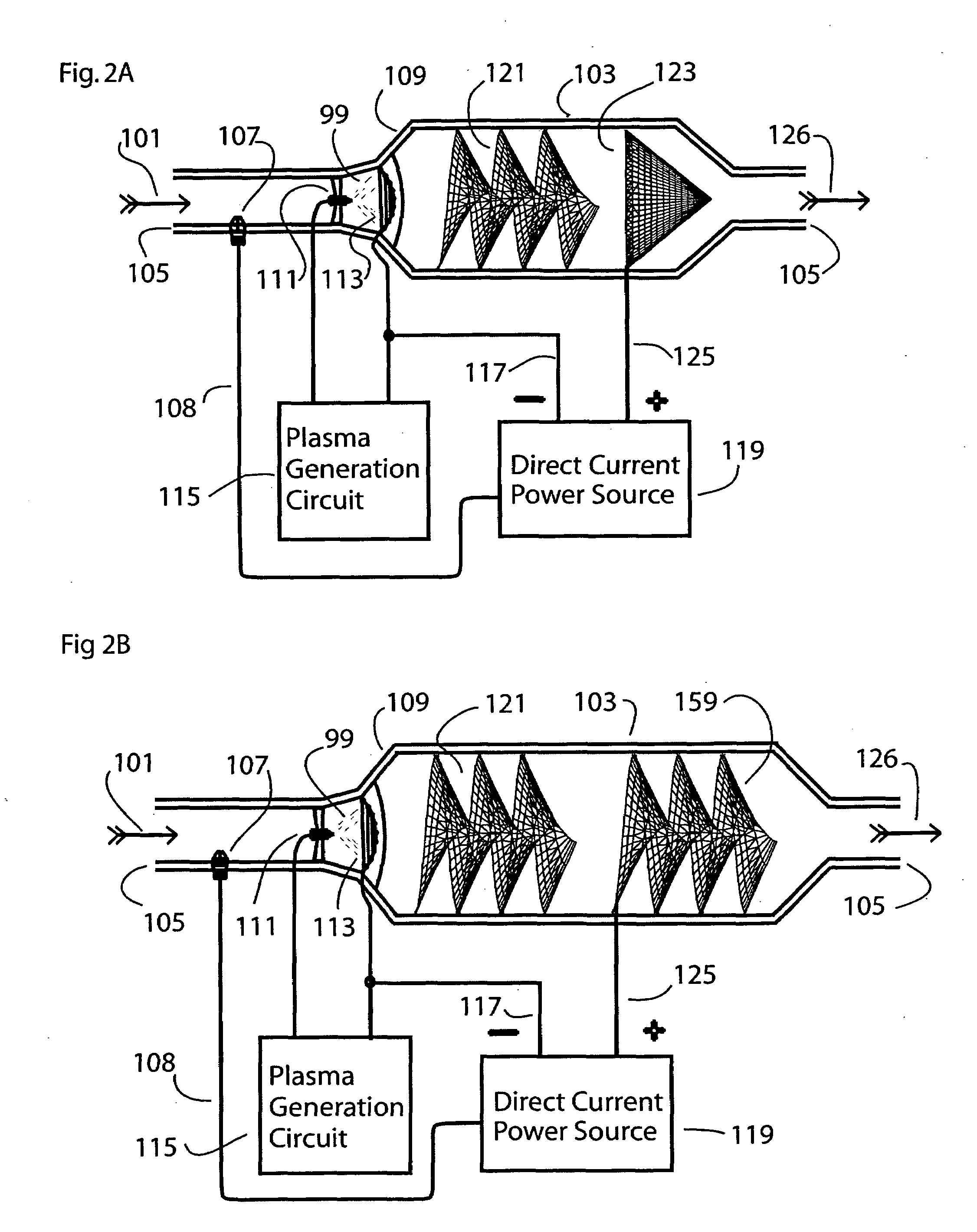
[0083]Referring to FIG. 1, the present invention is shown treating an exhaust output from a diesel engine 101 which enters a plasma oxidization reaction chamber 103 which is enclosed in an electrically insulated outer casing 105. As the gases to be treated flow in the first thing they encounter is a hydrocarbon pollutant level sensor 107 just before they are subjected to the first phase of the treatment process. This process is the ionization and the addition of electrons to the exhaust gases by a plasma discharge anode device 109 which consist...


PUM


Abstract

An apparatus and method for the breakdown of exhaust gas pollutant molecules into their constituent atoms and then re-assembling those atoms into low energy state non-toxic molecules that are found in the atmosphere naturally is disclosed. A plasma actuated electronic catalytic converter includes an exhaust gas inlet, a first oxidization reaction chamber, a second reduction reaction chamber, an exhaust gas outlet, and an electronics power source. A first reaction chamber includes a plasma discharge electrode and semi-spherical screen that are negatively biased by a direct current source followed by a mixing screen and an anode screen. A second reaction chamber includes a plasma discharge electrode and semi-spherical screen that are positively biased by a direct current source followed by a mixing screen, if needed, a fresh air inlet, and a screen or screens that are negatively biased so as to gradually return electrons to the exhaust gasses.

Description

CROSS REFERENCE TO RELATED APPLICATION[0001]This application is a nonprovisional application of U.S. Provisional Patent Application No. 60 / 901,306 filed on Feb. 15, 2007, currently pending. The disclosure of U.S. Provisional Patent Application No. 60 / 901,306 is hereby incorporated by reference.BACKGROUND OF THE INVENTION[0002]1. Field of the Invention[0003]The present invention relates to a method and apparatus for improving exhaust after-treatment devices for use by diesel and gasoline powered vehicles, generators, heavy equipment, industrial power sources, fuel burners and other sources of airborne pollutants from a wide variety of air pollution sources. Specifically, the invention includes a plasma electronic catalyst assisted molecular reformation of the elements within the exhaust gases into their least toxic and lowest energy molecular states, specifically, N2, CO2, and H2O, all of which occur naturally within the atmosphere.[0004]2. Description of the Related Art[0005]The ple...

Claims


Application Information

Patent Timeline
IPC IPC(8): F01N3/10
CPCF01N3/0892F01N2240/28F01N13/0093
Inventor JAYNE, MICHAEL E.KARL, JEFFREY J.
Owner JAYNE MICHAEL E
Why Eureka
Try Eureka