Plasma processing system, plasma measurement system, plasma measurement method, and plasma control system
- Summary
- Abstract
- Description
- Claims
- Application Information
AI Technical Summary
Benefits of technology
Problems solved by technology
Method used
Image

Examples
first modification
(First Modification)
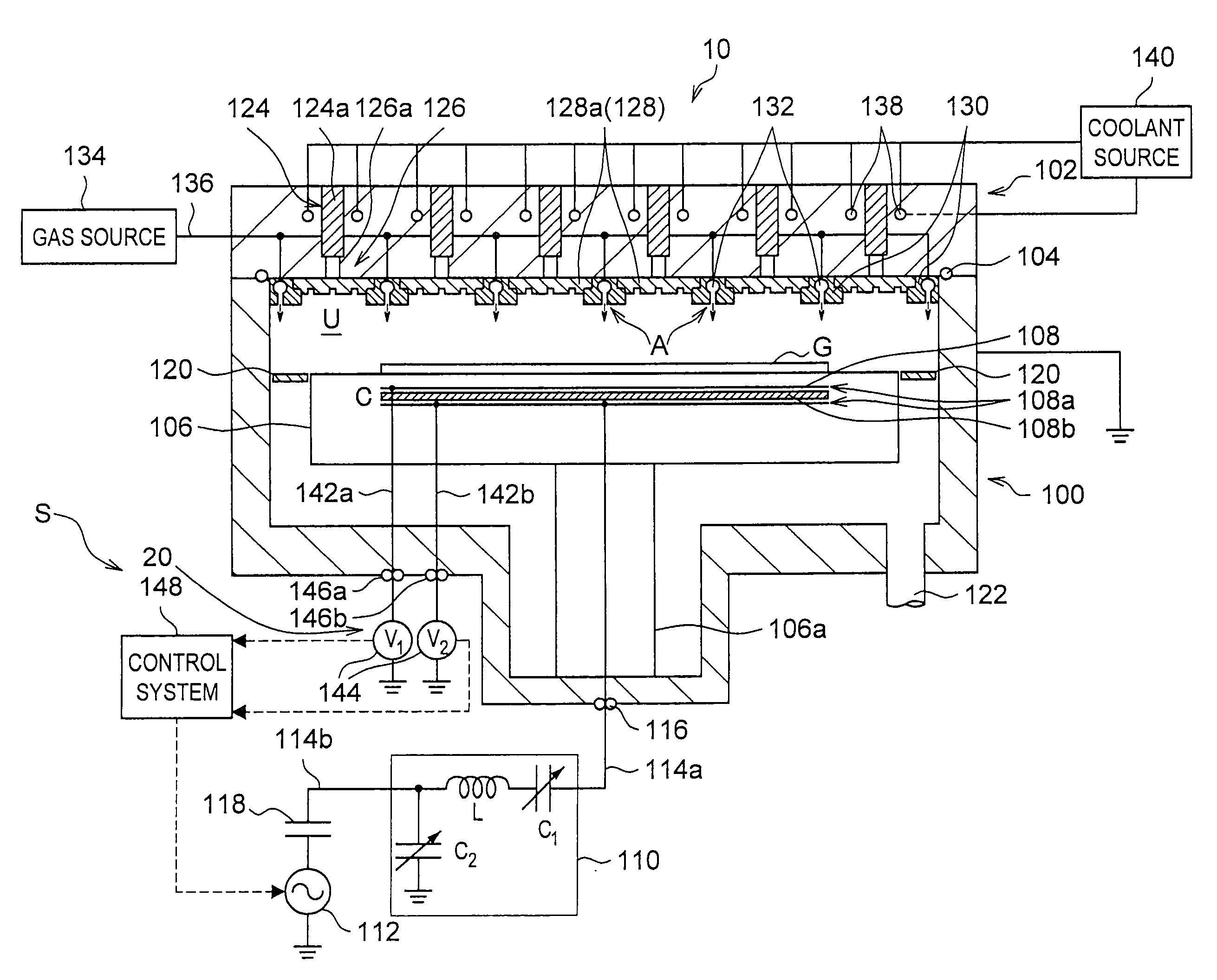
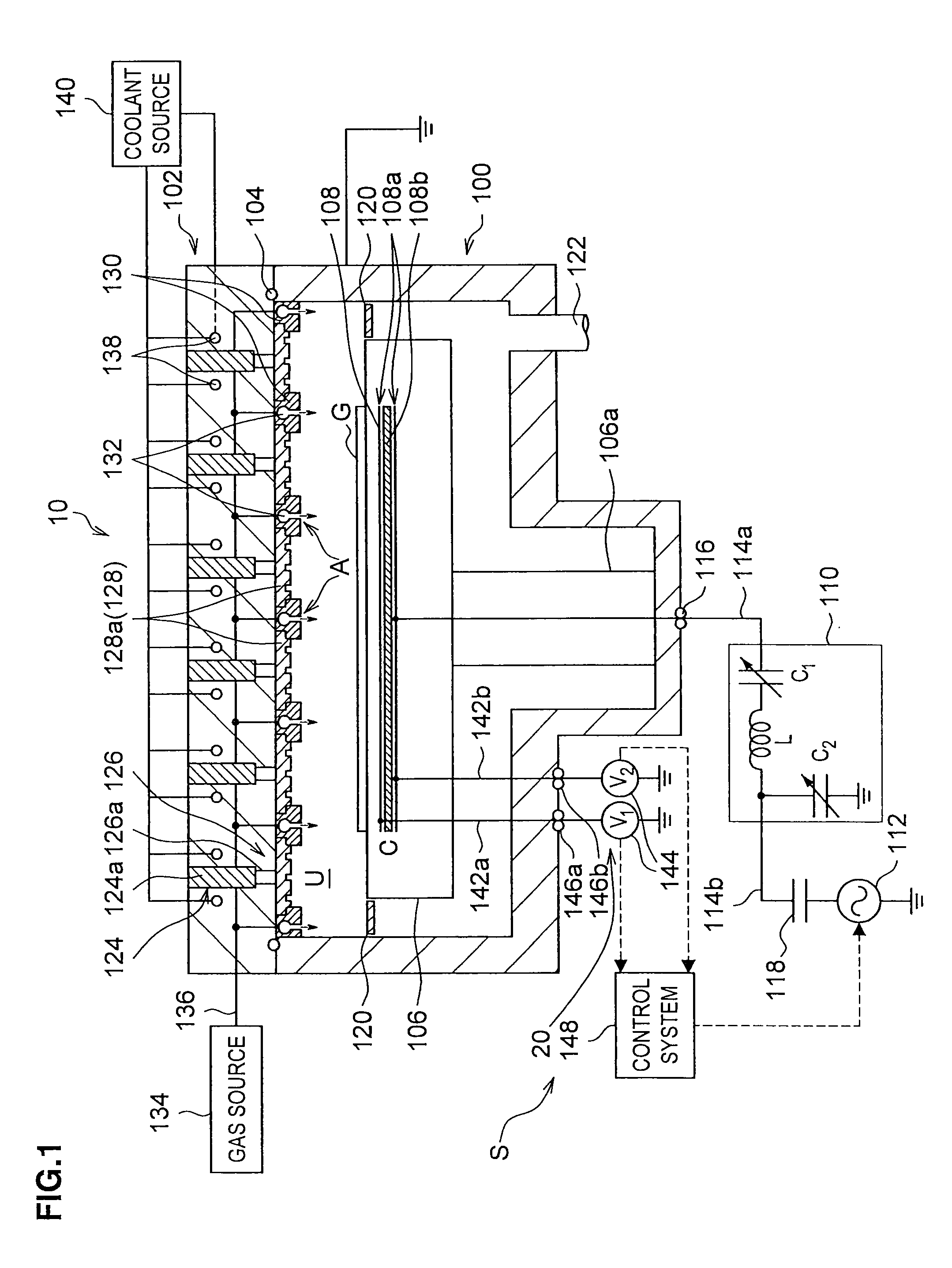
[0123]The second way proposed by the applicants to set the capacitance C of the capacitor 108a to 4.2 times or less than the sheath capacitance Csheath is as follows. With reference to FIG. 9, small electrodes (capacitor 108a) are formed at the end of the susceptor 106. This position is not opposed to the substrate G. i.e., has little effect on the plasma process.
[0124]In this method, like the first method, the voltages V1 and V2 at the pair of plates of the capacitor may be actually measured and the high-frequency electric power P of the susceptor 106 may be computed from the actual measurements, thereby deriving the high-frequency electric power immediately below the substrate, the electric power being available for the plasma control. Additionally, the method in the first modification may measure the voltages V1 and V2 with little effect on the plasma process. The capacitance of the capacitor 108a may easily be reduced. Note, however, that the voltages V1 and ...
second modification
(Second Modification)
[0125]The third way proposed by the applicants to set the capacitance C of the capacitor 108a to 4.2 times or less than the sheath capacitance Csheath is as follows. With reference to FIG. 10, the capacitor 108a is provided in the power feeding rod 106a below the susceptor 106, the capacitor 108a being connected to the power-supply line 114a.
[0126]Also in this method, the voltages V1 and V2 at the pair of plates of the capacitor 108a may be actually measured and the high-frequency electric power P of the susceptor 106 may be computed from the actual measurements, thereby deriving the high-frequency electric power immediately below the substrate, the electric power being available for the plasma control. Note, however, that a power leak from the bottom of the susceptor 106 to the processing chamber 100 may not be detected.
third modification
(Third Modification)
[0127]With reference to FIG. 11, for example, for any of the capacitors 108a shown in FIG. 1, FIG. 9, and FIG. 10, an inductor 150 as a resonance circuit (LC=1 / ω02; ω0 is a resonance frequency) may be connected in series with the capacitor 108a.
[0128]The load-impedance increase due to the capacitor 108a may thus be cancelled by the inductor 150 (serial resonance circuit), thereby reducing the impedance of the power-supply line 114a. The load of the matching box 110 may thus also be reduced.
[0129]According to the above embodiments and the modifications thereof, the capacitor 108a may be used to accurately measure the power immediately below the substrate.
[0130]Although in the above embodiments, the voltages of the electrical signals at the pair of plates of the capacitor 108a are measured as the parameters to control the plasma, the present invention is not limited thereto. At least one of the voltage, the current, and the phase at the pair of plates of the capac...
PUM
| Property | Measurement | Unit |
|---|---|---|
| Capacitance | aaaaa | aaaaa |
| Dielectric constant | aaaaa | aaaaa |
| Electric impedance | aaaaa | aaaaa |
Abstract
Description
Claims
Application Information
 - Generate Ideas
- Intellectual Property
- Life Sciences
- Materials
- Tech Scout
- Unparalleled Data Quality
- Higher Quality Content
- 60% Fewer Hallucinations
Browse by: Latest US Patents, China's latest patents, Technical Efficacy Thesaurus, Application Domain, Technology Topic, Popular Technical Reports.
© 2025 PatSnap. All rights reserved.Legal|Privacy policy|Modern Slavery Act Transparency Statement|Sitemap|About US| Contact US: help@patsnap.com