Process and System for Gasification with In-Situ Tar Removal

a gasification process and gasification system technology, applied in the field of gasification process and system with in-situ tar removal, can solve the problems of increasing the efficiency of all reactions, increasing the efficiency of conventional catalyst systems and methods, and related art failing to appreciate the ability for increased hydrogen (hsub>2/sub>) recovery, and simplifying downstream heat recovery and final gas clean up. , the effect of increasing hydrogen

Active Publication Date: 2008-10-09
TAYLOR BIOMASS ENERGY
View PDF43 Cites 92 Cited by
  • Summary
  • Abstract
  • Description
  • Claims
  • Application Information

AI Technical Summary

Benefits of technology

[0025]The product gas exiting the gasifier is conveyed through a gas-conditioning reactor prior to final cleanup. In this cracking reactor, the product gas is heated to approximately 1000° C. (1832° F.), the temperature of the heat transfer material returning to the gasification reactor from the combustion reactor, noted above. At 1000° C., the condensable hydrocarbons (tars) are cracked to form lower molecular weight compounds such as hydrogen (H2), Carbon Monoxide (CO), Benzene (C6H6), and Methane (CH4). This cracking step eliminates higher molecular weight materials from the gas thus substantially simplifying downstream heat recovery and final gas clean up for particulate material. Furthermore, the present invention provides for the further production of increased hydrogen using the adjustment of the hydrogen:carbon monoxide ratio by an in situ water gas shift reaction as noted in Equation 1.
[0026]As an additional benefit of the present invention, by removing condensable from the product gas, enhanced heat recovery is possible. When condensables remain in the product gas, the product gas may only be cooled to approximately 370° C. during heat recovery. After condensable removal however, heat recovery may occur at least as low as 200° C. resulting in approximately a 40% improvement in recovered energy from the product gas.

Problems solved by technology

Further, conventional catalyst systems and methods do not suppress carbon to the extent desired in the '653 patent.
Similarly, the related art fails to appreciate the benefit of a separate gas-conditioning module that is heated in situ at high system temperatures (1000° C. / 1800° F.) by a thermal transfer medium heated in a combustor module and recycles for continuous use, thereby increasing the efficiency of all reactions due to higher temperature use.
Furthermore, the related art fails to appreciate the ability for increased hydrogen (H2) recovery by including an in situ gas-conditioning module that operates at system high temperatures.
Finally, the related art in all cases fails to appreciate the use of steam in situ as a reactive to impact the water gas shift reaction in gas conditioning and thereby minimize the requirement for removal of condensables in a separate (ex situ) and costly downstream process

Method used


Image

  • Process and System for Gasification with In-Situ Tar Removal
  • Process and System for Gasification with In-Situ Tar Removal
  • Process and System for Gasification with In-Situ Tar Removal

Examples


Embodiment Construction

[0039]Reference will now be made in detail to several embodiments of the invention that are illustrated in the accompanying drawings. Wherever possible, same or similar reference numerals are used in the drawings and the description to refer to the same or like parts or steps. The drawings are in simplified form and are not to precise scale. For purposes of convenience and clarity only, directional terms, such as top, bottom, up, down, over, above, and below may be used with respect to the drawings. These and similar directional terms should not be construed to limit the scope of the invention in any manner. The words “connect,”“couple,” and similar terms with their inflectional morphemes do not necessarily denote direct and immediate connections, but also include connections through mediate elements or devices.

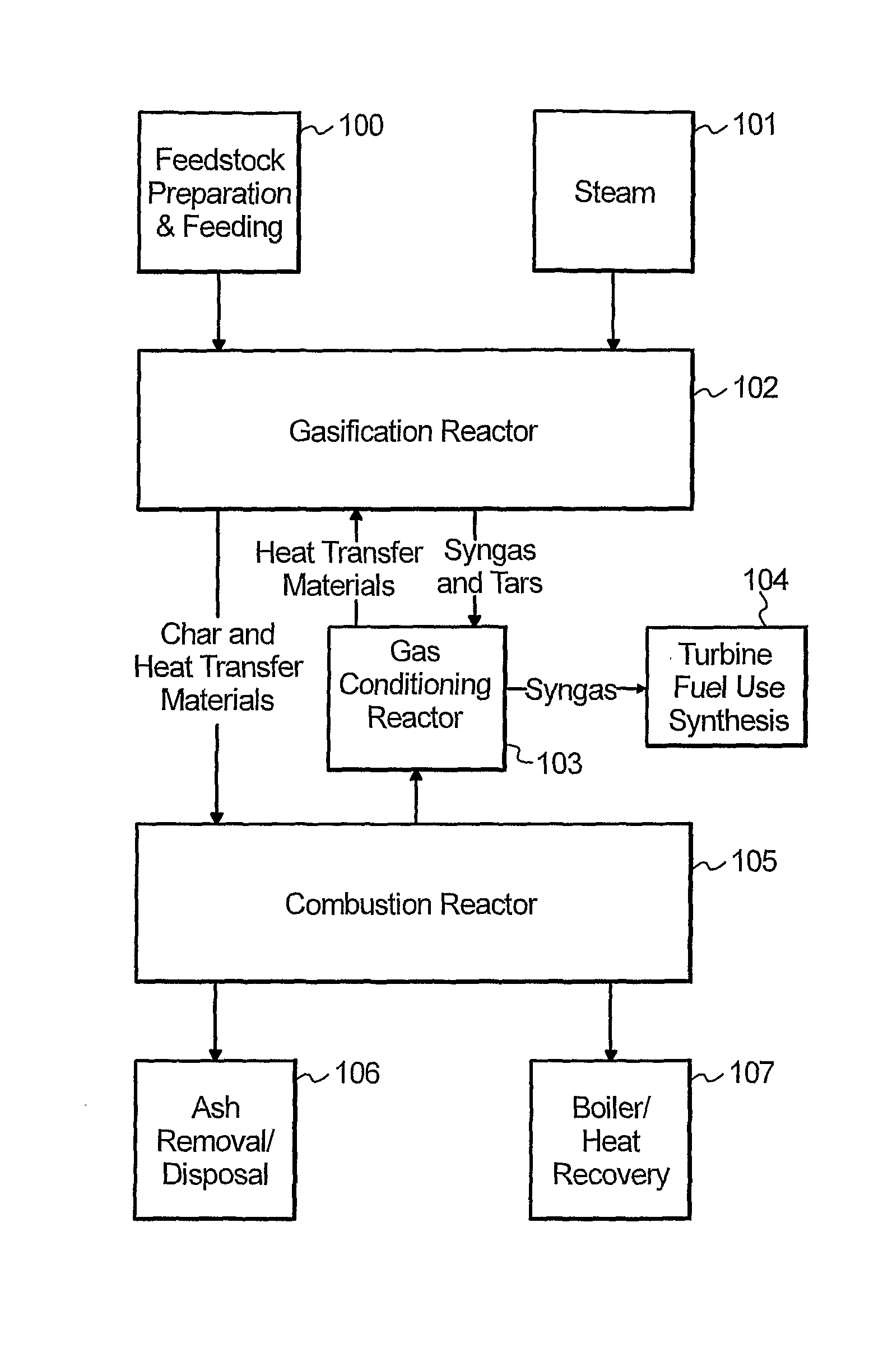
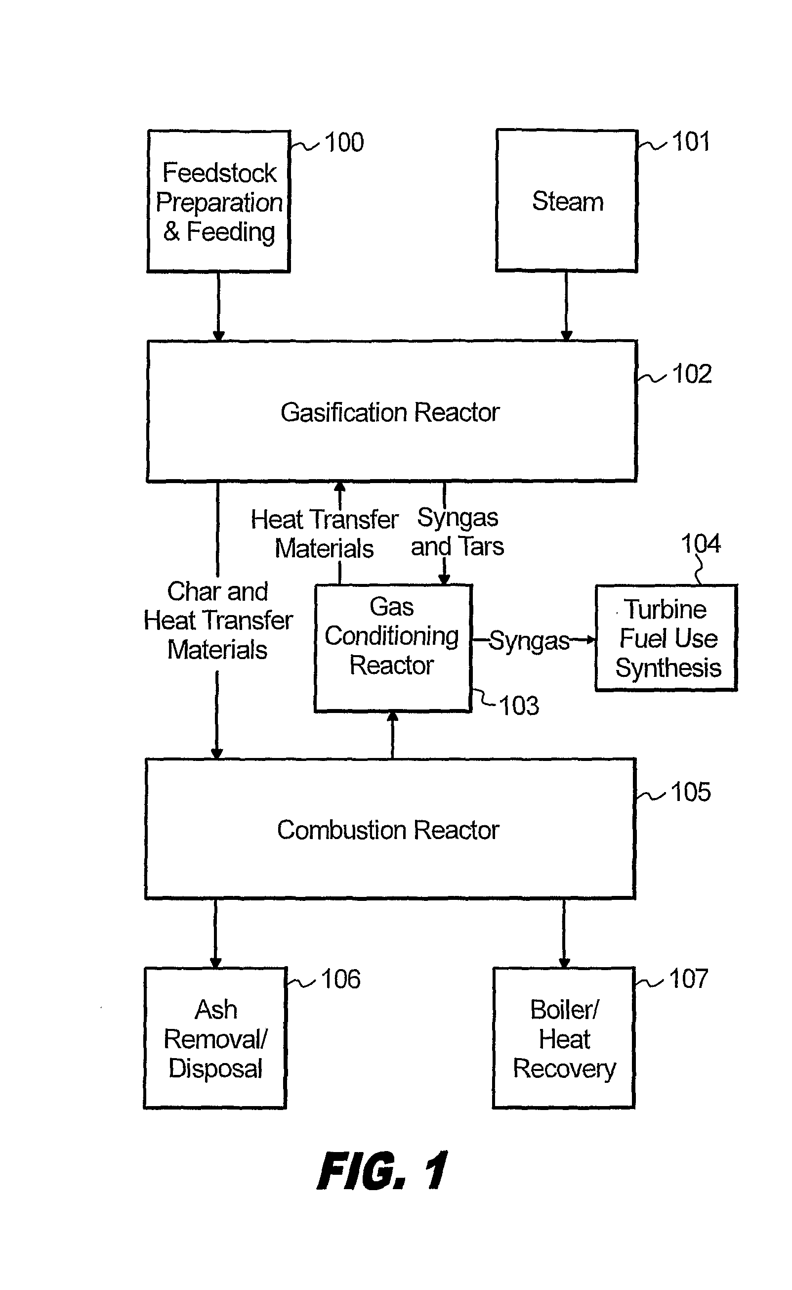
[0040]Referring now to FIG. 1 a schematic flow process of the present system is provided for gasifying biomass or other carbonaceous feed stocks in an indirectly heated gasif...


PUM

PropertyMeasurementUnit
velocityaaaaaaaaaa
velocityaaaaaaaaaa
temperatureaaaaaaaaaa

Abstract

The present invention relates to a process and system for gasifying biomass or other carbonaceous feedstocks in an indirectly heated gasifier and provides a method for the elimination of condensable organic materials (tars) from the resulting product gas with an integrated tar removal step. More specifically, this tar removal step utilizes the circulating heat carrier to crack the organics and produce additional product gas. As a benefit of the above process, and because the heat carrier circulates through alternating steam and oxidizing zones in the process, deactivation of the cracking reactions is eliminated.

Description

CROSS REFERENCE TO RELATED APPLICATIONS[0001]This application claims priority from U.S. Provisional App. Ser. No. 60 / 728,989, filed Oct. 21, 2005, the entire contents of which are herein incorporated by reference, and international application serial number PCT / US2006 / 041435 filed Oct. 23, 2006.FIGURE SELECTED FOR PUBLICATION[0002]FIG. 1BACKGROUND OF THE INVENTION[0003]1. Field of the Invention[0004]The present invention relates to a process and system for gasifying biomass or other carbonaceous feedstocks in an indirectly heated gasifier and a method for the elimination of condensable organic materials (tars) from the resulting product gas with an integrated tar removal step. More specifically this integral tar removal step utilizes the circulating heat carrier to crack the organics and produce additional product gas. As a benefit of the above process and because the heat carrier circulates through alternating steam and oxidizing zones in the process, deactivation of the cracking r...

Claims


Application Information

Patent Timeline
Patent Type & Authority Applications(United States)
IPC IPC(8): C01B3/44C01B3/36
CPCC07C4/04C10K3/04C10J3/84C10J2200/158C10J2300/0916C10J2300/0983C10J2300/1606C10J2300/1637C10J2300/165C10K3/008F23G2201/301F23G2201/304F23G2201/40Y02E20/16C10J3/482Y02P20/145C01B3/36C01B3/38C07C27/06
Inventor PAISLEY, MARK A.
Owner TAYLOR BIOMASS ENERGY
Why Eureka
Try Eureka