Apparatus and method for eliminating the breakthrough peak in differential detectors

a technology of differential detectors and breakthrough peak, applied in the field of differential detectors and comparative sensors, can solve the problems of a multitude of detectors or sensors susceptible to the same or similar problems, a large imbalance, and a breakthrough peak that distracts from the measuremen

Active Publication Date: 2008-10-09
MALVERN INSTRUMENTS
View PDF6 Cites 11 Cited by
  • Summary
  • Abstract
  • Description
  • Claims
  • Application Information

AI Technical Summary

Problems solved by technology

Differential detectors, comparative sensors or any other device that involves an analysis between two or more samples or specimen may result in a breakthrough peak that distracts from the measurement.
A multitude of detectors or sensors are susceptible to the same or similar problems.
Second, light reflects partially from surfaces that have a refractive index different from that of their surroundings.
The greater the RI difference between sample and mobile phase, the larger the imbalance will become.
This factor severely limits RI detector application in the analyses requiring the gradient elution, where the mobile phase composition is changed during the analysis to effect the separation.
This results in a change in the photon current falling on the detector that unbalances it.
The disadvantages are: a general disability to easily remove and clean or replace the cell when filming or clogging occurs, the need to flush the sample-side intermittently, static solvent causing baseline drift and the need to refresh, replenish or recharge the reference-side.
The disadvantages of the reflective detector are the incredible sensitivity to the flow and pressure fluctuations, and the need for changing prisms to accommodate either high or low RI solvents and the need to manually adjust the optical path when making solvent changes.
Presence of dissolved air, changes in solvent composition, improper mixing and column bleed will contribute to baseline drift.
All the above-noted apparatus, including differential detectors, comparative sensors or any device that involves an analysis between two or more samples or specimen, suffer from having a breakthrough peak that delays processing and contaminates flow paths and capillaries.

Method used


Image

  • Apparatus and method for eliminating the breakthrough peak in differential detectors
  • Apparatus and method for eliminating the breakthrough peak in differential detectors
  • Apparatus and method for eliminating the breakthrough peak in differential detectors

Examples


Embodiment Construction

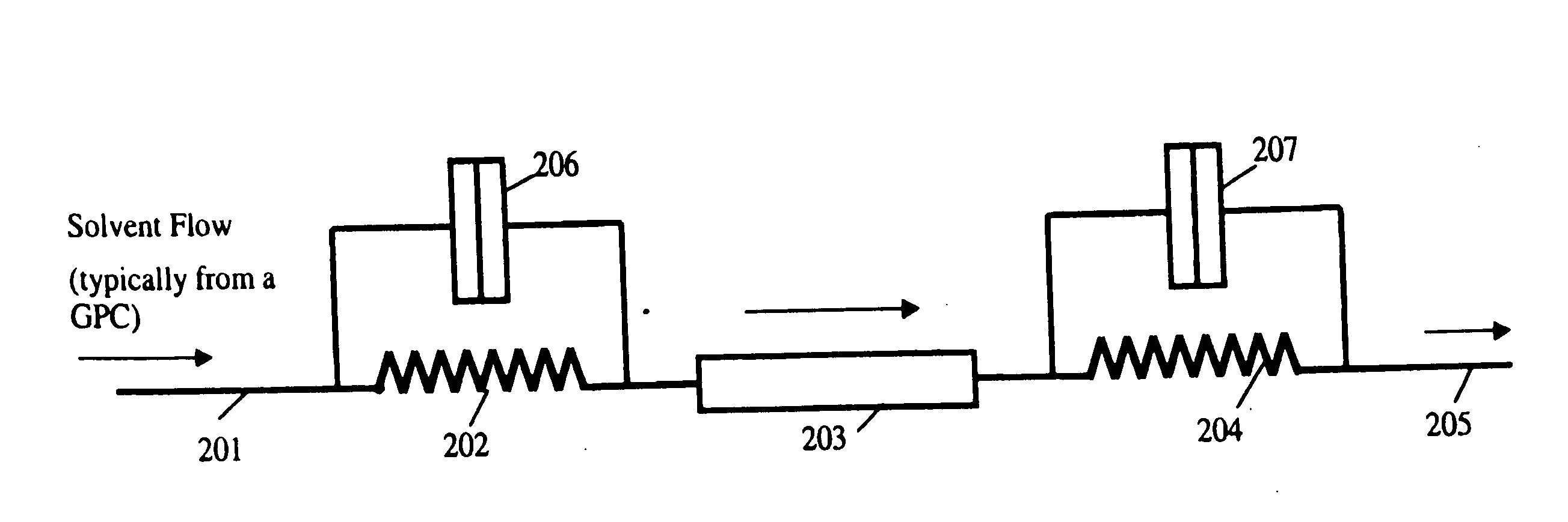
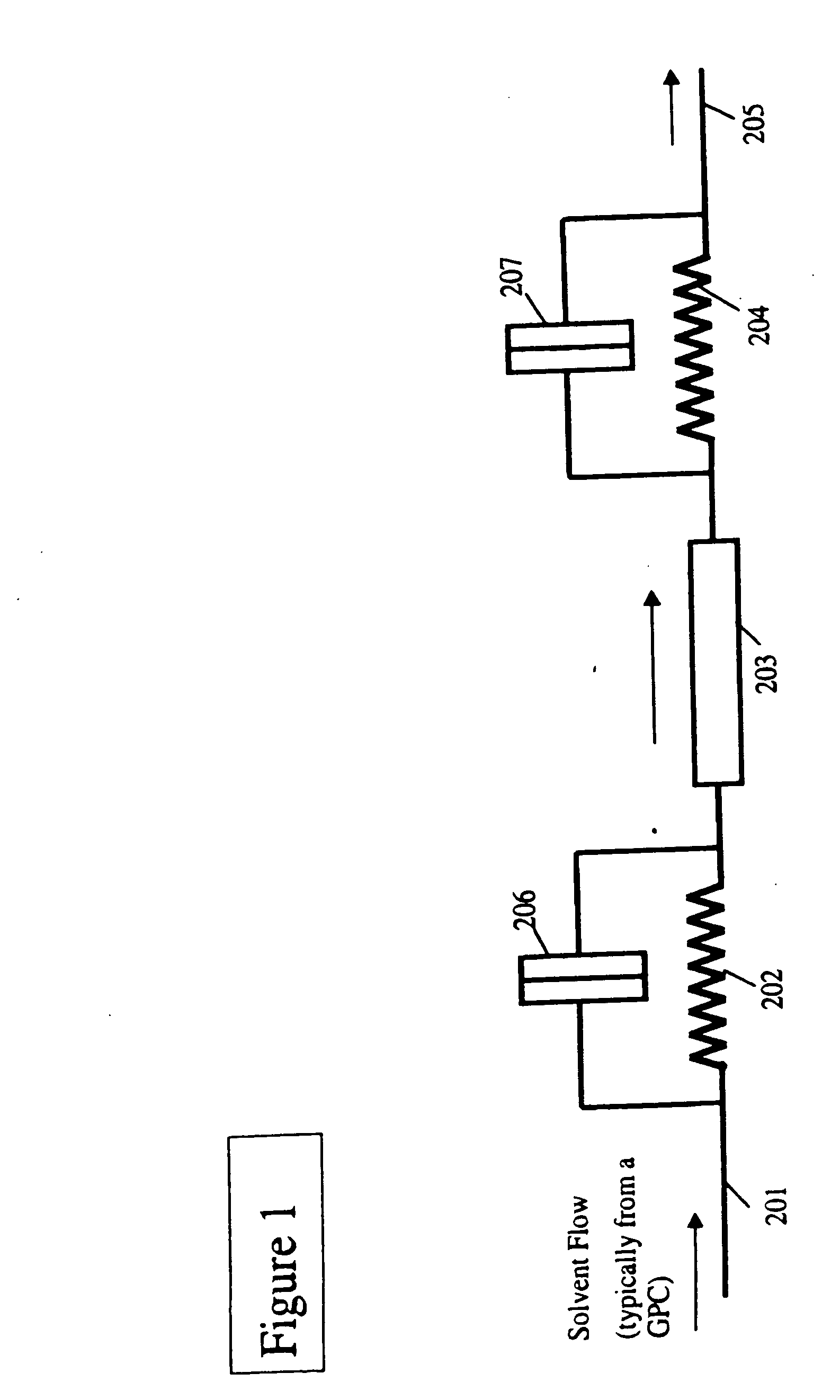
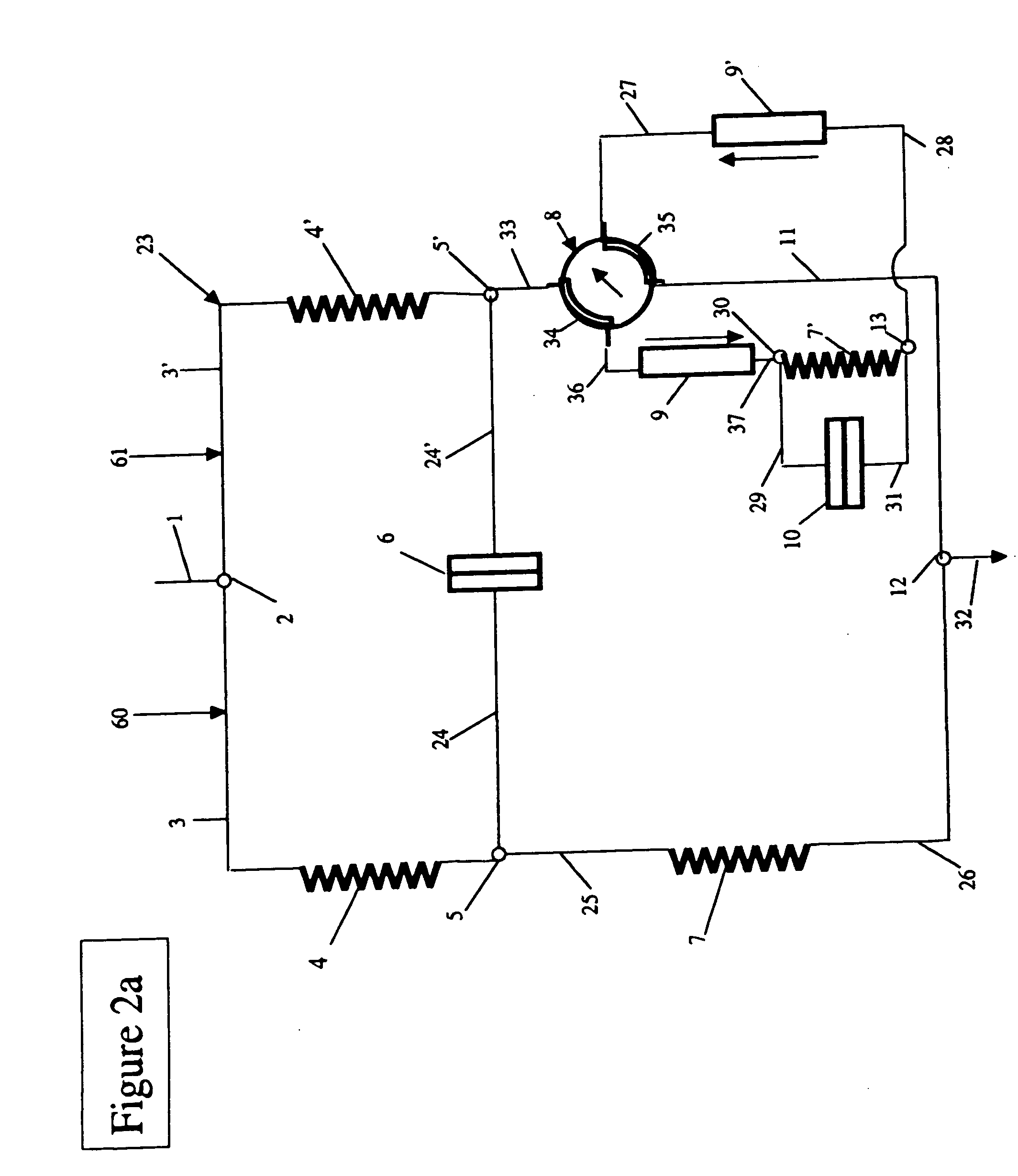
[0045]For a further understanding of the nature, function, and objects of the present invention, reference is made to the following detailed description taken in conjunction with the accompanying drawings. Detailed descriptions of embodiments of the apparatus are provided herein, as well as modes of carrying out and employing the embodiments of the present invention. It is to be understood, however, that the present apparatus may be embodied in various forms. The description provided herein relates to the common components of sample capillary, delay volume components, reference capillary and diverter valve which may form only part of a more complex circuit. Therefore, specific details disclosed herein are not to be interpreted as limiting, but rather as a basis for the claims and as a representative basis for teaching one skilled in the art to employ the present embodiments of one form of the apparatus or method in virtually any appropriately detailed system, structure or manner. Th...


PUM

PropertyMeasurementUnit
refractive indexaaaaaaaaaa
delay volumesaaaaaaaaaa

Abstract

The method comprising the steps of engaging the flow circuit of the detector with a reference fluid, accepting a sample in the flow circuit of the detector, sensing an attribute of the sample for determining a characteristic of the sample, changing the direction of the flow of the sample in the flow circuit, and purging the sample from the flow circuit such that the flow circuit is ready to accept another sample. Another method provides the steps of engaging the flow circuit of the detector with a reference fluid, inserting a sample in the flow circuit juxtaposed to the reference fluid, sensing an attribute of the sample for determining a characteristic of the sample, and deviating the direction of the flow of the sample from the flow circuit for purging the sample from the flow circuit such that the reference fluid is maintained in the flow circuit.The apparatus comprises a detector for analyzing a sample comprising a reference cell and a sample cell such that the detector is charged with a reference fluid, a switching valve in communication with the sample cell of the detector, and one or more delay volumes and the reference cell in communication with the switching valve. The sample is juxtaposed the reference fluid for engaging the sample cell for analysis, the analyzed sample engages the switching valve for alternately diverting the analyzed sample from the flow circuit and for maintaining the detector charged with the reference fluid.

Description

CROSS REFERENCE TO RELATED APPLICATION[0001]The present application is a continuation-in-part application of the application of Alan Titterton, U.S. Ser. No. 11 / 249,839, filed Oct. 12, 2005, entitled IMPROVED MULTI-CAPILLARY VISCOMETER APPARATUS AND METHOD, now U.S. Pat. No. 7,334,457 issued Feb. 26, 2008.FIELD OF THE INVENTION[0002]The present invention relates to differential detectors, comparative sensors or any device that involves an analysis between two or more samples or specimen. More particularly, the present invention relates to eliminating the breakthrough peak associated with differential detectors, comparative sensors or any device that involves an analysis between two or more samples or specimen.BACKGROUND OF THE INVENTION[0003]Differential detectors, comparative sensors or any other device that involves an analysis between two or more samples or specimen may result in a breakthrough peak that distracts from the measurement. A multitude of detectors or sensors are susc...

Claims


Application Information

Patent Timeline
Patent Type & Authority Applications(United States)
IPC IPC(8): G01N11/00G01N30/02
CPCG01N11/08G01N30/02G01N30/32G01N30/74G01N33/442G01N2011/0006G01N2030/621B01D15/34G01N2021/4146
Inventor TITTERTON, ALANHANEY, MAX A.
Owner MALVERN INSTRUMENTS
Why Eureka
Try Eureka