Dynamoelectric coil portion insulating construction

a technology of insulating construction and coil, which is applied in the manufacture of dynamo-electric machines, dynamo-electric machines, electrical equipment, etc., can solve the problems of high adhesion strength, early insulation failure, and affect the service life of enamel coatings, so as to reduce the hardness of insulating resin, high heat resistance, and high adhesion strength

Inactive Publication Date: 2008-10-09
MITSUBISHI ELECTRIC CORP +1
View PDF4 Cites 16 Cited by
  • Summary
  • Abstract
  • Description
  • Claims
  • Application Information

AI Technical Summary

Benefits of technology

[0012]According to the present invention, the uppermost layer of the enamel coating of the enameled wire is a soft polyamideimide resin layer that has high heat resistance, and the THEIC-modified polyester resin, which constitutes a major component of the insulating resin and which has high heat resistance, is modified by the oil component, reducing the hardness of the insulating resin. Thus, stresses that arise between the conductor of the enameled wire and the insulating resin are alleviated, reducing damage to the enamel coating.
[0013]It is particularly necessary for dynamoelectric machines such as automotive alternators, etc., that are mounted to vehicles to endure use for long periods such as 15 years, 150,000 km, etc., for example, and coil portion insulating constructions that can be used therein are required not only to have strong initial adhesive forces but also to maintain strong adhesive forces over long periods. In a coil portion insulating construction according to the present invention, because the THEIC-modified polyester resin that constitutes a major component of the insulating resin 26 is modified by the oil component, reactions in the insulating resin are slowed down, and strong adhesive forces and increased insulation can be maintained not only when new, but also for long periods, making the present invention eminently suitable for coil portion insulating constructions in dynamoelectric machines that are mounted to vehicles.

Problems solved by technology

Since automotive alternators of this kind are exposed to high temperatures and vibrations for long periods, not only initial adhesive strength is required of the insulating resin of the coil portion insulating construction, but also adhesive strength that is high for long periods.
Thus, one problem has been that the service life of enamel coatings may be affected if compatibility between the enamel coatings and the insulating resins is poor, giving rise to early insulation failure.
Because the enameled wires are bent and deformed in the process of winding the enameled wires, large mechanical loads act on the enameled wires, imparting damage to the enamel coatings.
Since the epoxy-modified polyesterimide resin that is disclosed in Patent Literature 1 has extremely rigid properties, large shearing stresses may arise between the insulating resin and the enamel coatings if the epoxy-modified polyesterimide resin is used as the insulating resin, imparting damage to the enamel coatings and reducing the service life of the enamel coatings.

Method used


Image

  • Dynamoelectric coil portion insulating construction
  • Dynamoelectric coil portion insulating construction
  • Dynamoelectric coil portion insulating construction

Examples


embodiment 1

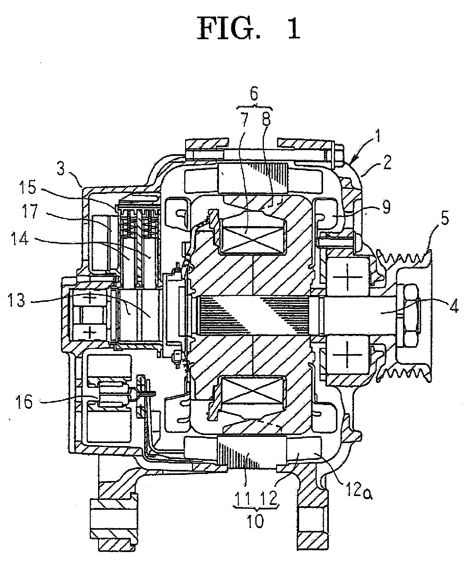
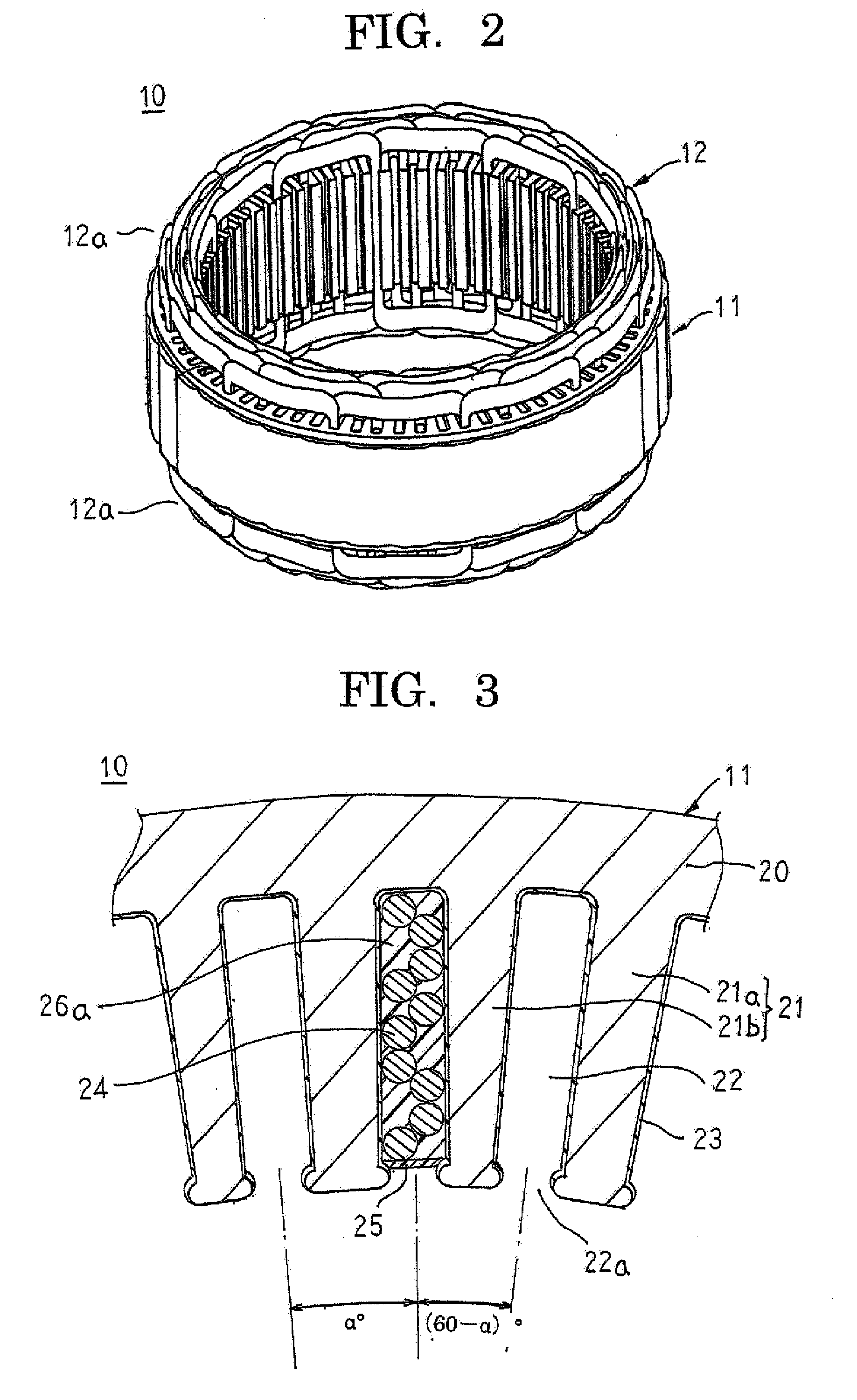
[0031]FIG. 1 is a cross section of an automotive alternator to which an insulating construction according to Embodiment 1 of the present invention has been applied, FIG. 2 is a perspective of a stator to which the insulating construction according to Embodiment 1 of the present invention has been applied, FIG. 3 is a partial cross section of the stator that is shown in FIG. 2, FIG. 4 is a cross section of a stator coil that constitutes a stator winding of the stator that is shown in FIG. 2, and FIG. 5 is a diagram that explains a step of applying an insulating resin to the stator that is shown in FIG. 2. FIGS. 6A through 6C are diagrams that explain a thermal degrading action of the insulating resin that can be used in the insulating construction according to Embodiment 1 of the present invention, FIG. 6A representing a liquid state of the insulating resin, FIG. 6B representing a solid state after heat hardening of the insulating resin, and FIG. 6C representing a loosely cross-linke...

embodiment 2

[0064]In Embodiment 1 above, a coil portion insulating construction according to the present invention was applied to an automotive alternator stator, but in Embodiment 2, a coil portion insulating construction according to the present invention is applied to an automotive alternator rotor.

[0065]FIGS. 10A and 10B are diagrams that explain a configuration of a wound portion of a field coil of a rotor to which an insulating construction according to Embodiment 2 of the present invention has been applied, FIG. 10A being a cross section thereof and FIG. 10B being a partial cross section thereof. FIG. 11 is a cross section of the field coil of the rotor to which the insulating construction according to Embodiment 2 of the present invention has been applied, FIG. 12 is a diagram that explains a step of applying an insulating resin in Embodiment 2 of the present invention, and FIGS. 13A through 13C are diagrams that explain a thermal degrading action of the insulating resin that can be use...

embodiment 3

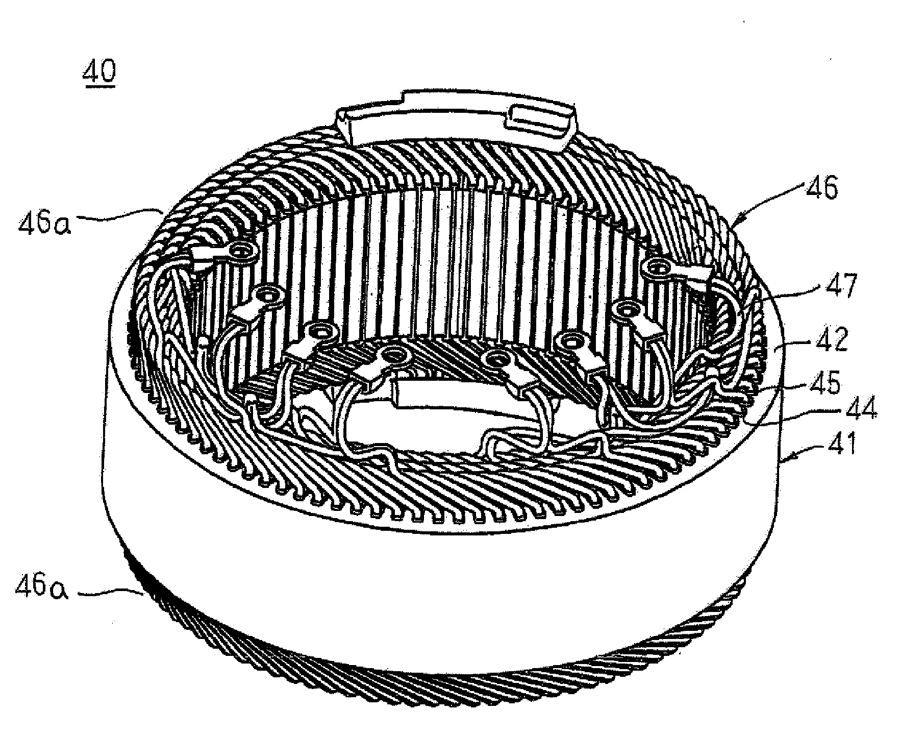
[0089]FIG. 15 is a perspective of a stator to which an insulating construction according to Embodiment 3 of the present invention has been applied, FIG. 16 is a plan of a winding assembly that constitutes a stator winding of the stator that is shown in FIG. 15, and FIGS. 17A and 17B are diagrams that explain a method for manufacturing the stator that is shown in FIG. 15.

[0090]In FIGS. 15 through 17B, a stator 40 includes: a stator core 41; and a stator winding 46 that is installed in the stator core 41.

[0091]The stator core 41 includes: an annular core back portion 42; a plurality of tooth portions 43 that are disposed so as to extend radially inward from the core back portion 42; and a plurality of slot portions 44 that are defined by the core back portion 42 and the tooth portions 43. The tooth portions 43 are constituted by tooth portions 43a that have a large circumferential width and narrow tooth portions 43b. The tooth portions 43a and 43b are disposed alternately such that an...


PUM


Abstract

A stator coil 24 is installed in a stator core 11, and an insulating resin is impregnated into slot portions 22 and hardened. The stator coil 24 is constituted by enameled wires in which a polyamideimide resin layer has been applied radially outside a copper wire and hardened, and the insulating resin contains as a major component a THEIC-modified polyester resin that has been modified by a fatty acid.

Description

BACKGROUND OF THE INVENTION[0001]1. Field of the Invention[0002]The present invention relates to a coil portion insulating construction for a dynamoelectric machine such as an automotive alternator, etc., and particularly relates to an insulating construction for a stator coil, or a field coil, etc.[0003]2. Description of the Related Art[0004]In conventional automotive alternators, coil portions that are formed by winding enameled wire onto a stator core, or a rotor core, etc., have been impregnated with insulating resins such as unsaturated polyester resins, or polyester resins to which epoxy resins have been added, etc., to increase insulation of the coil portions.[0005]Coil portion insulating constructions in which enameled wires that have enamel coatings that have polyamideimide resin layers were used and epoxy-modified polyesterimide resins were used as insulating resins have been disclosed, such as in Patent Literature 1, for example.[Patent Literature 1][0006]Japanese Patent ...

Claims


Application Information

Patent Timeline
Patent Type & Authority Applications(United States)
IPC IPC(8): H02K15/12
CPCH02K3/345H02K15/12
Inventor ASAO, YOSHIHITOKATAYAMA, HIROKITOKUYAMA, HITOSHIMAKINO, TOMOTAKA
Owner MITSUBISHI ELECTRIC CORP
Why Eureka
Try Eureka