
Brushless motor

a brushless motor and motor technology, applied in the direction of motor/generator/converter stopper, dynamo-electric converter control, shape/form/construction, etc., can solve the problems of difficult to find new mechanisms for improving motor efficiency, difficult to constitute single-phase motor as brushless motor, and easy damage to switching components and capacitors, etc., to improve the power energy of single-phase motor, improve the effect of power consumption and excellent technology

Inactive Publication Date: 2008-10-09
GK BRIDGE 1
View PDF19 Cites 22 Cited by
  • Summary
  • Abstract
  • Description
  • Claims
  • Application Information

AI Technical Summary

Benefits of technology

[0012]An object of the present invention is to provide a technique of improving motor efficiency. Another object of this invention is to provide a single-phase brushless motor that can start up without having a deadlock point, and without an auxiliary coil.
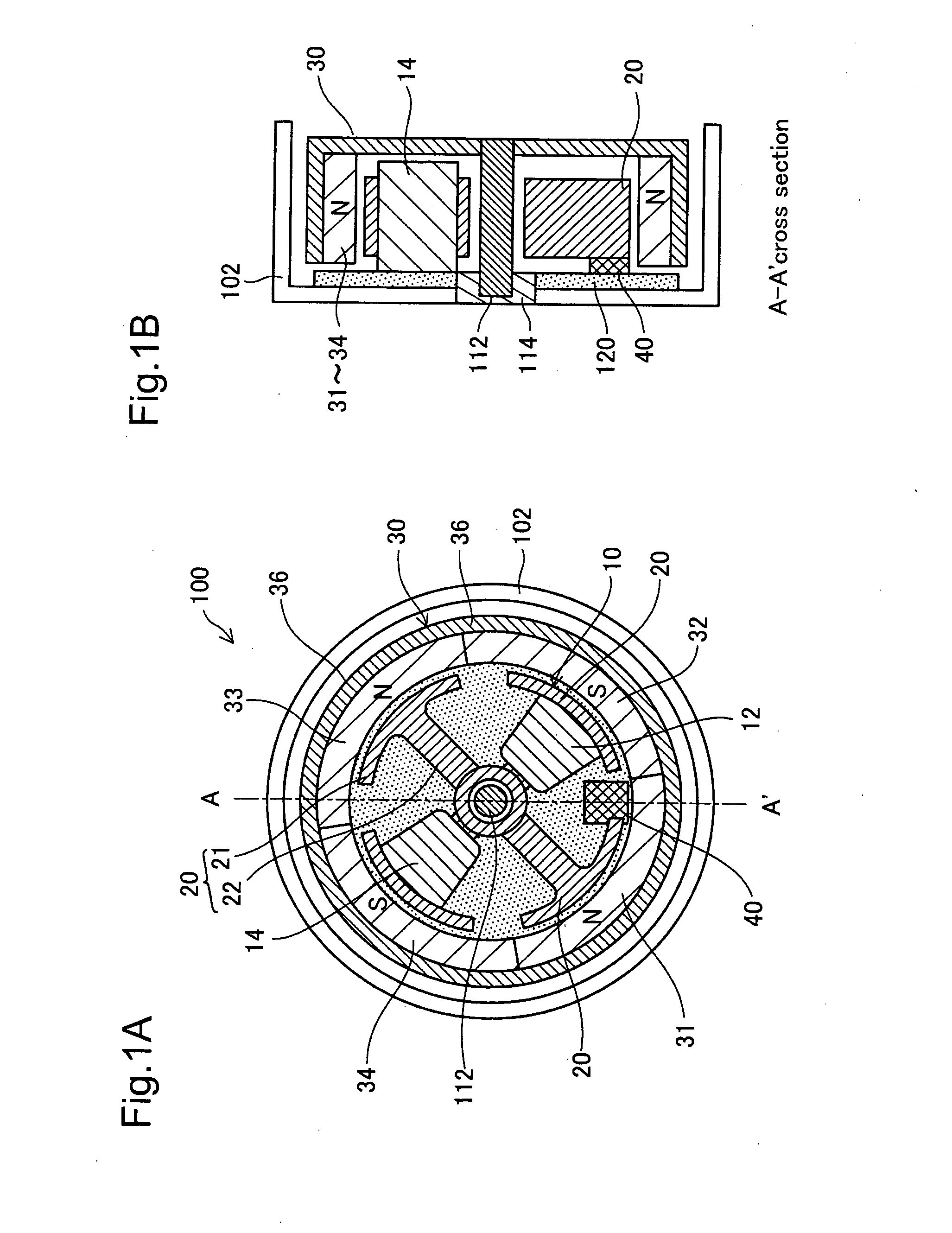
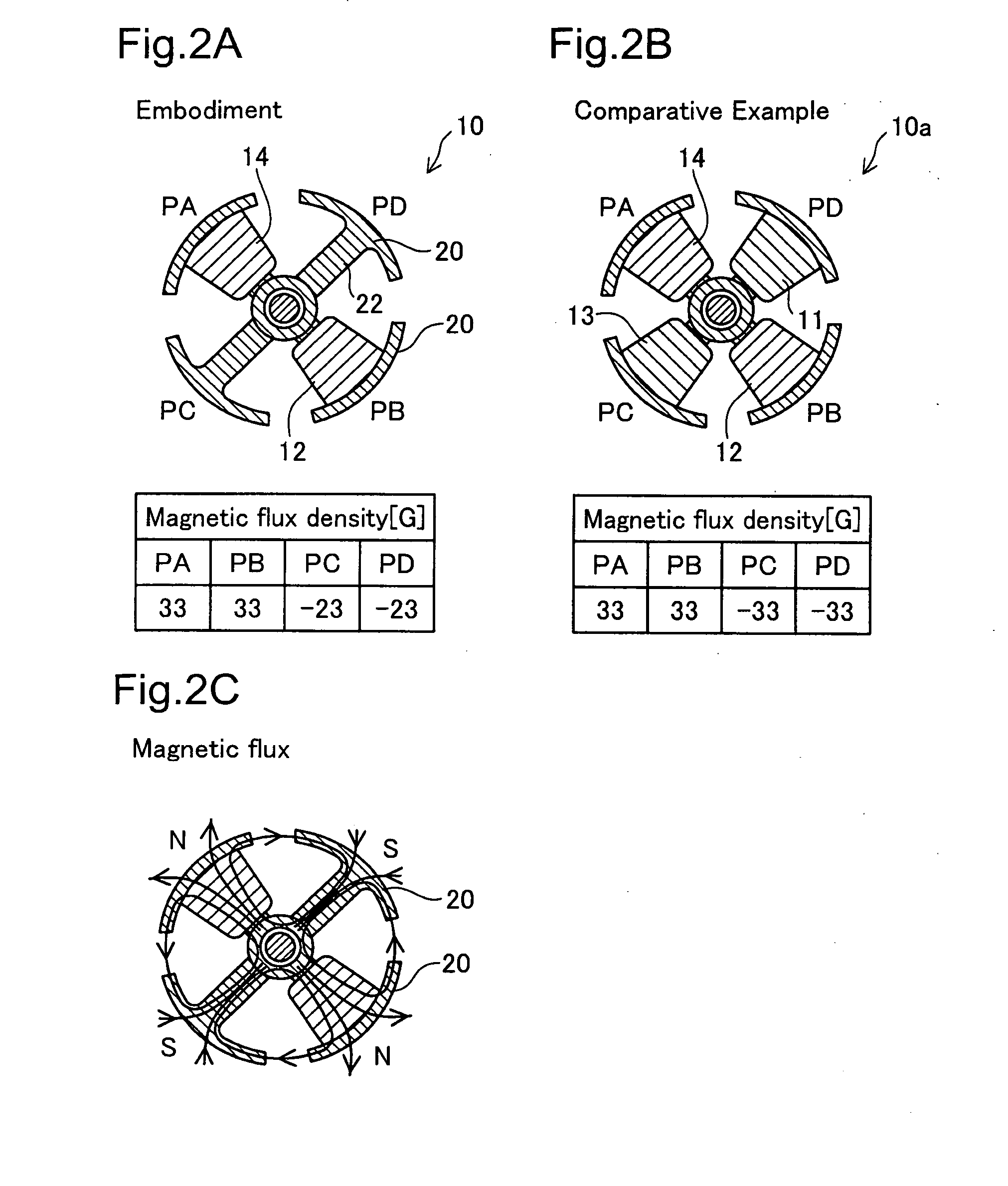
[0014]With this brushless motor, the electromagnetic coil is coiled on the magnetic body core selected regularly at a ratio of 1 to 2M from among the arrangement of the 2 (M×N) magnetic body cores, so it is possible to omit the number of electromagnetic coils, and to reduce the copper loss due to the electromagnetic coils, making it possible to improve the efficiency. Also, for magnetic body cores on which an electromagnetic coil is not coiled as well, fairly large magnetic flux is generated in the reverse direction of the magnetic flux that is generated with the magnetic body core for which an electromagnetic coil is coiled, so there is no excessive decrease in motor output.

Problems solved by technology

However, as a result of improvements in motors over many years, in recent years, it has become difficult to find new mechanisms for improving motor efficiency.
Regarding brushless motors, there have further been the following kinds of problems.
However, when the single-phase motor is started up using inverter drive, a large current is flowed to the auxiliary coil or capacitor during startup, so the problem arises of damage to the switching component and capacitor occurring easily.
In this way, there has been the problem that constituting the single-phase motor as a brushless motor is difficult.

Method used


Image

  • Brushless motor
  • Brushless motor
  • Brushless motor

Examples


modification examples

D. MODIFICATION EXAMPLES

[0109]The present invention is not limited to the embodiments described hereinabove, and may be reduced to practice in various other ways without departing from the spirit thereof. Modifications such as the following would be possible, for example.

modification example 1

D1. Modification Example 1

[0110]While analog magnetic sensors are employed in the preceding embodiments, it is possible to use digital magnetic sensors having multivalue analog output, instead of analog magnetic sensors. Both an analog magnetic sensor and a digital magnetic sensor with multivalue analog output will have an output signal exhibiting analog variation. Herein, an “output signal exhibiting analog variation” refers in the broad sense to include both analog output signals, and multilevel digital output signals having three or more levels, not On / Off binary output.

[0111]It is also acceptable to use a digital magnetic sensor with binary digital output, instead of a sensor with an output signal exhibiting analog variation. In this case, the ADC 570 and the excitation interval setting unit 590 of FIG. 12A will not be necessary. Consequently, while the failure to set the excitation interval and to use a sine wave drive waveform will result in lower efficiency and the occurrence...

modification example 2

D2. Modification Example 2

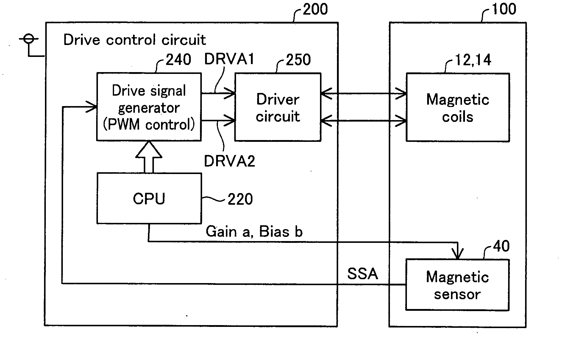
[0112]It is possible to employ as the PWM circuit various circuit configurations besides that shown in FIG. 12A For example, it is possible to use a circuit that performs PWM control by comparing a sensor output with a triangular reference wave. It is also possible to employ a circuit that generates drive signals by some method besides PWM control. For example, a circuit that amplifies sensor output and generates an analog drive signal may be used.

[0113]In FIG. 12A, the ADC 570 may be replaced with a voltage comparator. In this case, the drive waveform will be rectangular rather than a sine wave drive waveform, and thus noise / vibration will occur, but it will be possible to realize the drive control circuit by an inexpensive IC.


PUM


Abstract

The brushless motor has a first and second drive member. The first drive member is equipped with M phase coil groups each having N electromagnetic coils where M is an integer of 1 or greater and N is an integer of 1 or greater. The second drive member has a plurality of permanent magnets, and is able to move relative to the first drive member. The first drive member has 2 (M×N) magnetic body cores. Each phase electromagnetic coil is coiled on a periodically selected magnetic body core at a ratio of 1 to 2M from among the arrangement of 2 (M×N) magnetic body cores.

Description

CROSS-REFERENCE TO RELATED APPLICATIONS[0001]The present application claims the priority based on Japanese Patent Applications No. 2007-101599 filed on Apr. 9, 2007, and No. 2008-1585 filed on Jan. 8, 2008, the disclosures of which are hereby incorporated by reference in their entireties.BACKGROUND OF THE INVENTION[0002]1. Field of the Invention[0003]This invention relates to a brushless motor using permanent magnets and electromagnetic coils.[0004]2. Description of the Related Art[0005]In the motor industry, both one-phase motors and two-phase motors are collectively called “single phase motors.” However, with the description below, “single phase motor” means only one-phase motors, and excludes two-phase motors.[0006]A brushless motor using permanent magnets and electromagnetic coils is disclosed, for example, in JP2001-298982A.[0007]With this prior art brushless motor, control is performed using on / off signals from digital magnetic sensors. In specific terms, the timing of the pol...

Claims


Application Information

Patent Timeline
Patent Type & Authority Applications(United States)
IPC IPC(8): H02K29/08H02K21/00H02P6/16H02P6/08
CPCH02K21/16H02K29/03H02P6/008H02P6/16H02P6/22H02P6/26
Inventor TAKEUCHI, KESATOSHISUGIMOTO, MAMORUSEJIMO, ISAMUNAKAMURA, KAZUYOSHI
Owner GK BRIDGE 1
Learn More