
Transparent Optical Film Comprising Damage Prevention Layer Having Particles Distributed Therein

a technology of optical film and damage prevention layer, which is applied in the field of optical film, can solve the problems of affecting so as to improve the quality of optical film, and prevent the attachment of impurities

Inactive Publication Date: 2008-10-09
KOLON IND INC
View PDF10 Cites 11 Cited by
  • Summary
  • Abstract
  • Description
  • Claims
  • Application Information

AI Technical Summary

Benefits of technology

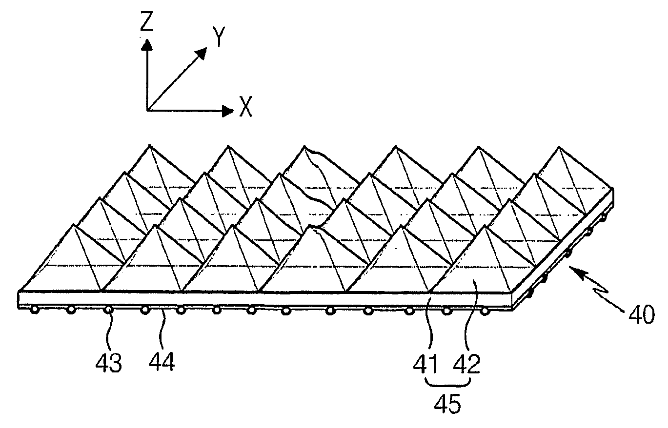
[0023]The present invention has been made keeping in mind the above problems occurring in the prior art, and an object of the present invention is to provide a transparent optical film having an improved prism structure, usable as a prism sheet, which functions to prevent the prism structure and the other surface of the optical film from damage due to external impact, vibration and friction, and also, to prevent the attachment of impurities due to frictional static charges.
[0024]Another object of the present invention is to provide a transparent optical film, which has improved optical properties, such as front luminance.

Problems solved by technology

Although a CRT (Cathode Ray Tube) is typically used in the electronic display device, limitations are imposed on manufacturing the CRTs at large sizes because the space to mount bulky CRTs is difficult to provide.
However, when the two prism sheets are laminated, the prism structure may be worn due to impact or vibration during the manufacturing process or when using the LCD.
In addition, the smooth surface of the upper sheet may be scratched due to contact with the vertices of the prisms of the lower sheet.
As for manufacturing the film, the prism structure may be damaged due to surface friction with the film loading device, and due to friction between the prism films when separating the respective loaded optical films.
In particular, the smooth surface may be easily damaged.
The material generally used for the prism film, such as polyethyleneterephthalate or polycarbonate, has relatively low surface hardness, and causes severe damage.
Moreover, the likelihood of impurities becoming attached to the smooth surface due to static charges caused by friction during transport or assembly is increased.
Thus, the damage to the prism structure or smooth surface or attachment of impurities results in formation of non-uniform shapes or images when transmitting light.
Thereby, it is impossible to realize a uniform and clear image, causing high defect rates.

Method used


Image

  • Transparent Optical Film Comprising Damage Prevention Layer Having Particles Distributed Therein
  • Transparent Optical Film Comprising Damage Prevention Layer Having Particles Distributed Therein
  • Transparent Optical Film Comprising Damage Prevention Layer Having Particles Distributed Therein

Examples


example 1

[0049]90 parts by weight of acrylic polyol and 10 parts by weight of isocyanate were dissolved in 300 parts by weight of methylethylketone and 200 parts by weight of toluene. 10 parts by weight of polymethylmethacrylate (PMMA) particles (average diameter 5 μm, monodispersed particles) and 2 parts by weight of quaternary amine-based antistatic agent were dispersed in the above solution. Subsequently, the obtained solution was applied on one surface of a 125 μm thick base film formed of polyethyleneterephthalate using gravure, and dried at 100° C. for 30. sec, to prepare a sheet including a damage prevention layer composed of 6 μm thick portions in which particles were distributed and 4 μm thick portions in which no particles were distributed.

[0050]A mixture of 95 parts by weight of an acryl-based UV curing resin and 5 parts by weight of a light initiator was applied on the surface opposite the damage prevention layer of the sheet, and exposed to UV, to manufacture an optical film hav...

example 2

[0051]90 parts by weight of acrylic polyol and 10 parts by weight of isocyanate were dissolved in 300 parts by weight of methylethylketone and 200 parts by weight of toluene. 20 parts by weight of PMMA particles (average diameter 5 μm, monodispersed particles) and 2 parts by weight of quaternary amine-based antistatic agent were dispersed in the above solution. The subsequent processes were performed in the same manner as in Example 1, to manufacture an optical film.

example 3

[0052]90 parts by weight of acrylic polyol and 10 parts by weight of isocyanate were dissolved in 300 parts by weight of methylethylketone and 200 parts by weight of toluene. 20 parts by weight of PMMA particles (average diameter 5 μm, monodispersed particles) and 2 parts by weight of quaternary amine-based antistatic agent were dispersed in the above solution.

[0053]Subsequently, unlike Example 1, the obtained solution was applied on one surface of a 125 μm thick base film formed of polyethyleneterephthalate using gravure, and dried at 100° C. for 30 sec, to prepare a sheet including a damage prevention layer composed of 6 μm thick portions in which particles were distributed and 2 μm thick portions in which no particles were distributed. In addition, on the surface opposite the damage prevention layer of the sheet, a mixture of 95 parts by weight of an acryl-based UV curing resin and 5 parts by weight of a light initiator was applied, and exposed to UV, to manufacture an optical fi...


PUM


Abstract

Disclosed herein is a transparent optical film, including an optically structured layer, which is a sheet formed of a transparent polymeric material and composed of a first surface having three-dimensional structures thereon and a second surface opposite the first surface, and a damage prevention layer formed on the second surface of the optically structured layer and composed of a transparent polymeric material and spherical organic or inorganic particles. The damage prevention layer has protruding surface portions formed by the particles protruding from the transparent polymeric material. The optical film of the current invention is advantageous because the prism structure and the opposite surface of the optical film are prevented from damage due to external impact, vibration and friction, and the attachment of impurities due to frictional static charges is prevented. Further, the front luminance and optical properties of the optical film are improved.

Description

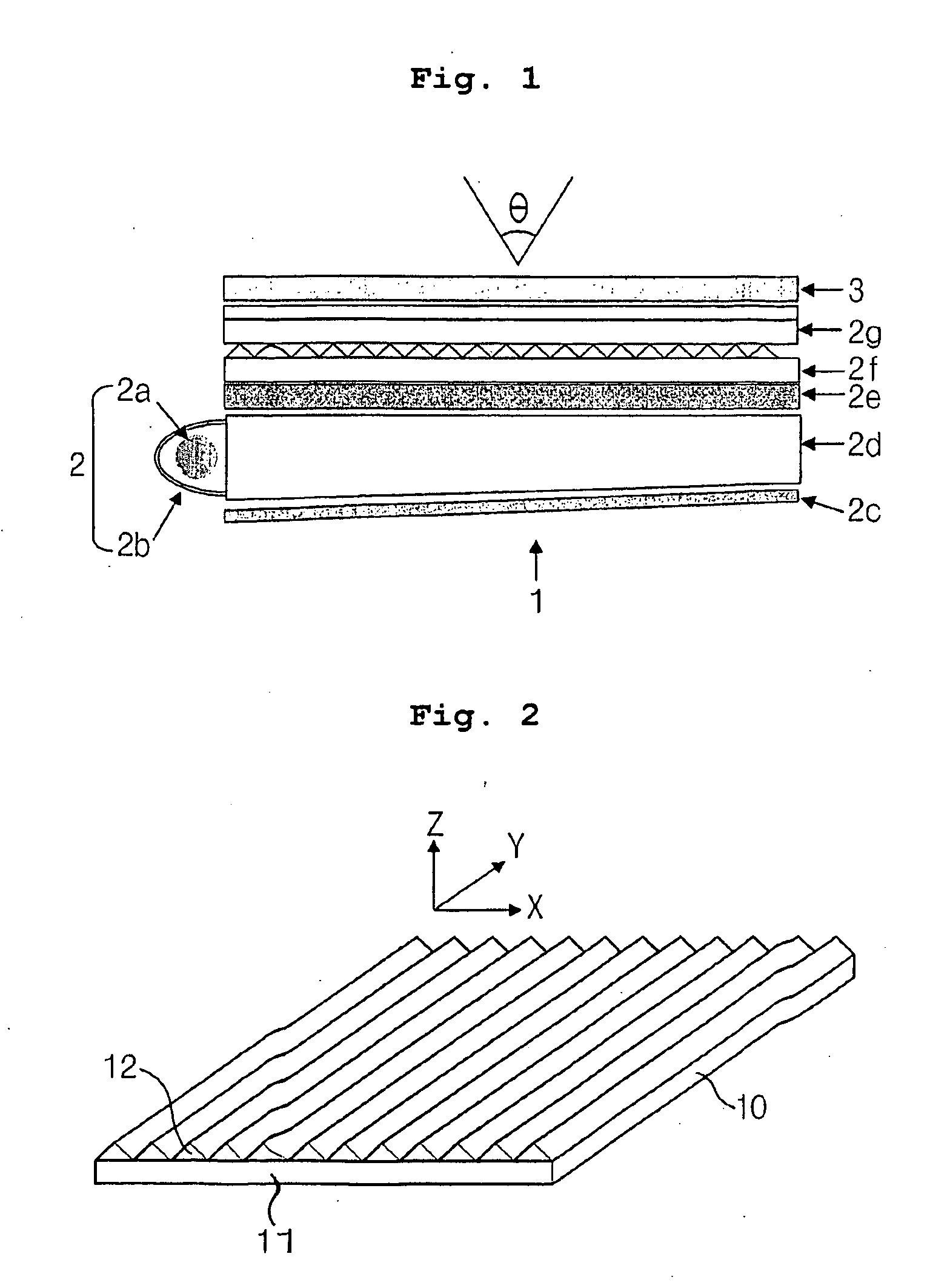
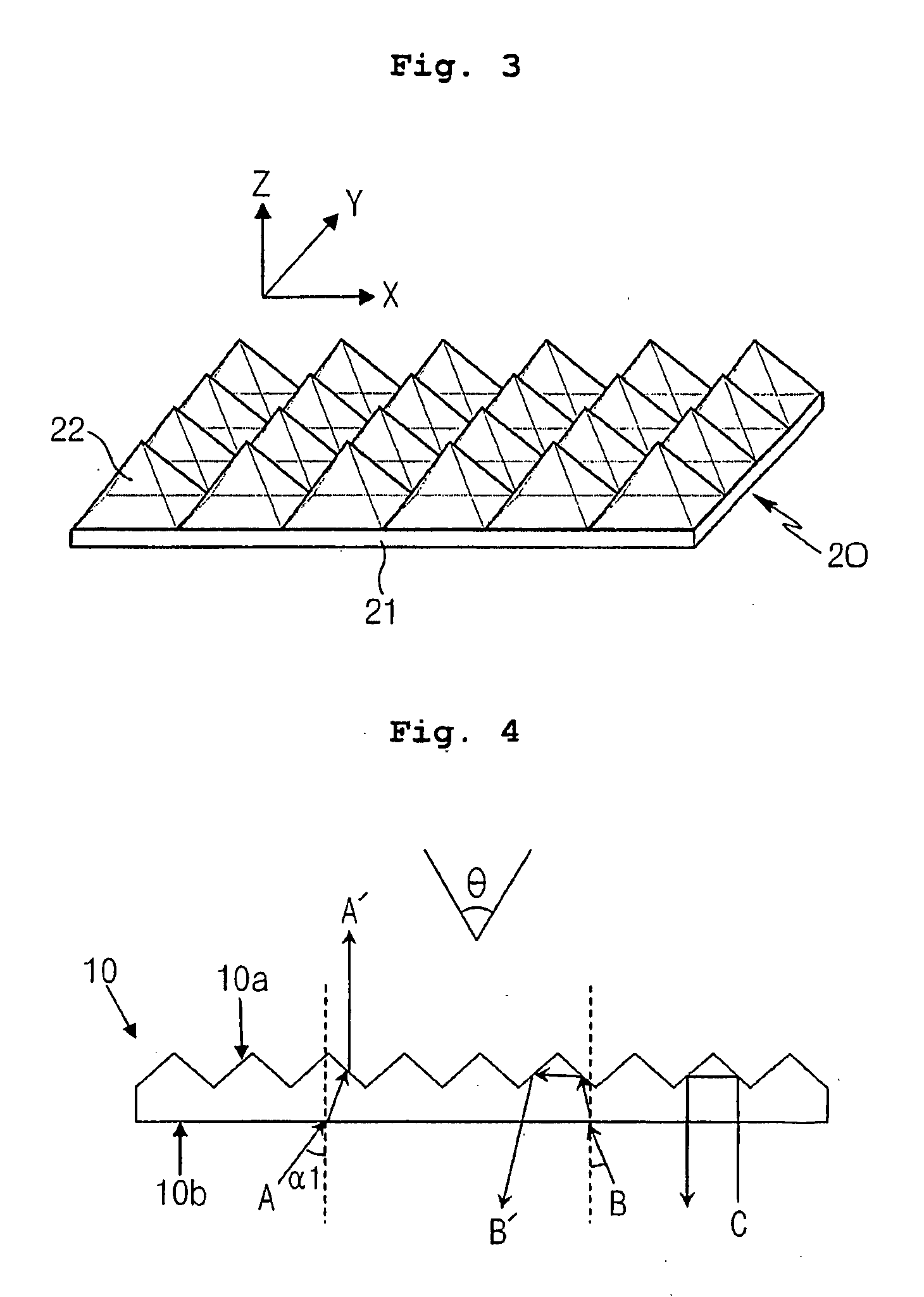
TECHNICAL Field[0001]The present invention relates, in general, to an optical film for use in a liquid crystal display (LCD), and, more particularly, to a transparent optical film, which is used in a backlight unit of an LCD to increase the efficiency of light transfer from a light source to an LCD panel, thus increasing the luminance of an image reproduced on the screen and realizing a uniform image of high quality over the entire screen.BACKGROUND ART[0002]As industrialized society has been developed towards a high information age, electronic display devices have become increasingly important as a medium for displaying and transferring various pieces of information. Although a CRT (Cathode Ray Tube) is typically used in the electronic display device, limitations are imposed on manufacturing the CRTs at large sizes because the space to mount bulky CRTs is difficult to provide. Thus, such a CRT tends to be replaced with various flat displays, such as LCDs, plasma display panels (PDP...

Claims


Application Information

Patent Timeline
IPC IPC(8): B32B3/00F21V8/00G02F1/1335
CPCG02B6/0036G02B6/0038Y10T428/24612A61B5/7475G06Q50/22
Inventor KIMPARK, JONG MINKIM, CHANG GUNKIM, JI SEONGJUNG, WOO CHUL
Owner KOLON IND INC
Learn More