
Regenerative adsorption processes for removing organic components from gas streams

Inactive Publication Date: 2008-10-16
BAYER MATERIALSCIENCE AG
View PDF11 Cites 4 Cited by
  • Summary
  • Abstract
  • Description
  • Claims
  • Application Information

AI Technical Summary

Benefits of technology

[0009]Various embodiments of the present invention can provide processes which are more advantageous in terms of energy and which, in particular, reduce the use of expensive inert gases during the regeneration of the adsorbers and permit a continuous process.
[0010]Various embodiments of the processes according to the present invention can provide reduced inert gas consumption in regenerative adsorption processes for process gas purification of gas streams contaminated with organic compounds.
[0029]M) optional subsequent increase of the pressure of the purified circulating inert gas stream, in particular with the aid of a circulating gas compressor, in order to overcome any circulating gas pressure losses;

Problems solved by technology

One disadvantage of such a process is that the production process and the HCl purification process must be interrupted for regeneration of the activated carbon bed.
A further disadvantage of such a process is that the regeneration is conducted thermally or at reduced pressure, which is disadvantageous in terms of energy, or is carried out using an inert gas, which is expensive.
Steam can only be used in cases where moisture can be tolerated within the process.
When inert gases (e.g. nitrogen, etc.) are used in regeneration, however, the amounts of gas that must be used to provide a continuous stream of fresh regenerative gas give rise to high costs.
Otherwise, the regeneration achieved would not be sufficient to provide the required process gas purities during the adsorption operation.

Method used


Image

  • Regenerative adsorption processes for removing organic components from gas streams
  • Regenerative adsorption processes for removing organic components from gas streams
  • Regenerative adsorption processes for removing organic components from gas streams

Examples


example 1

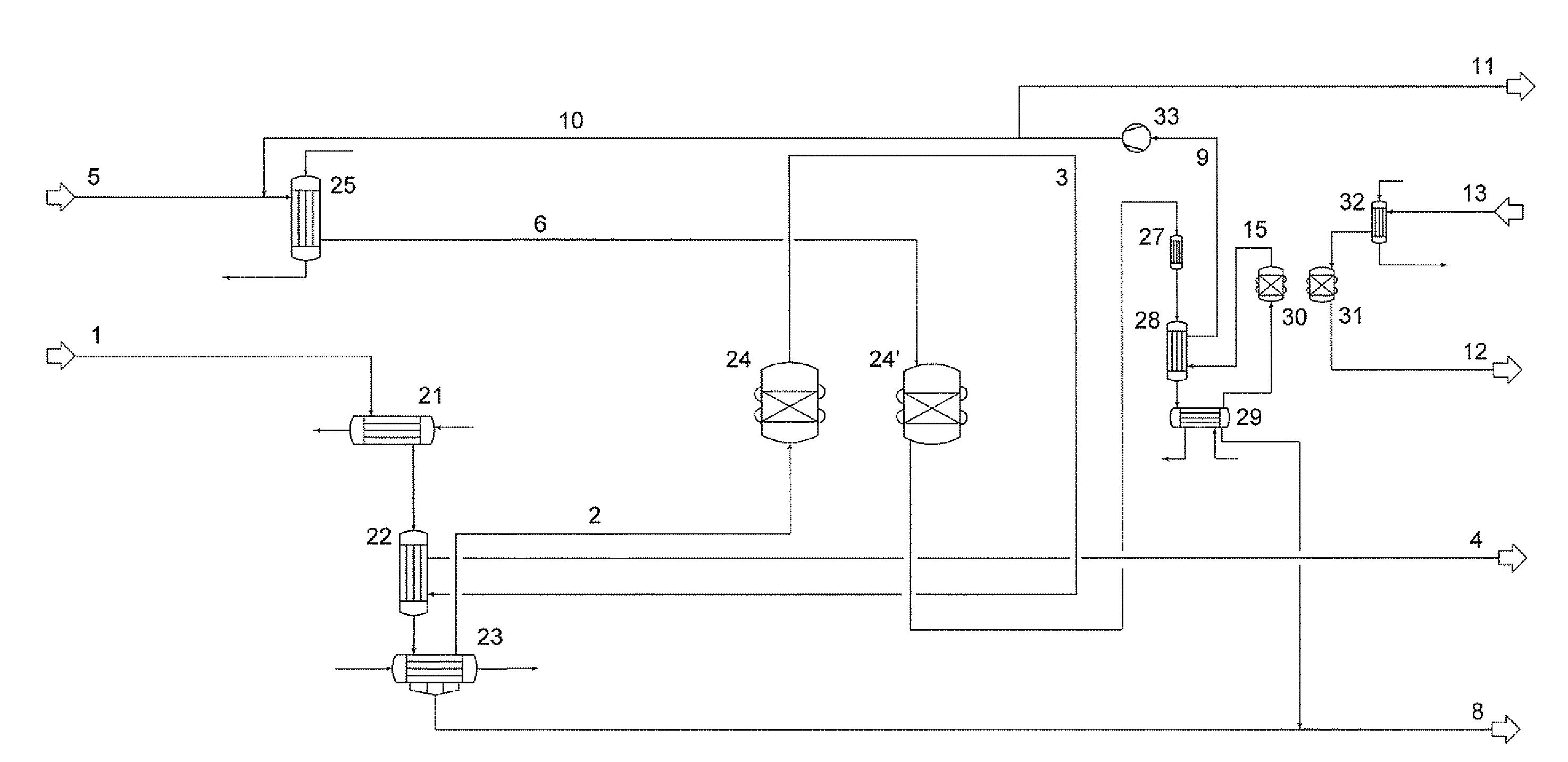
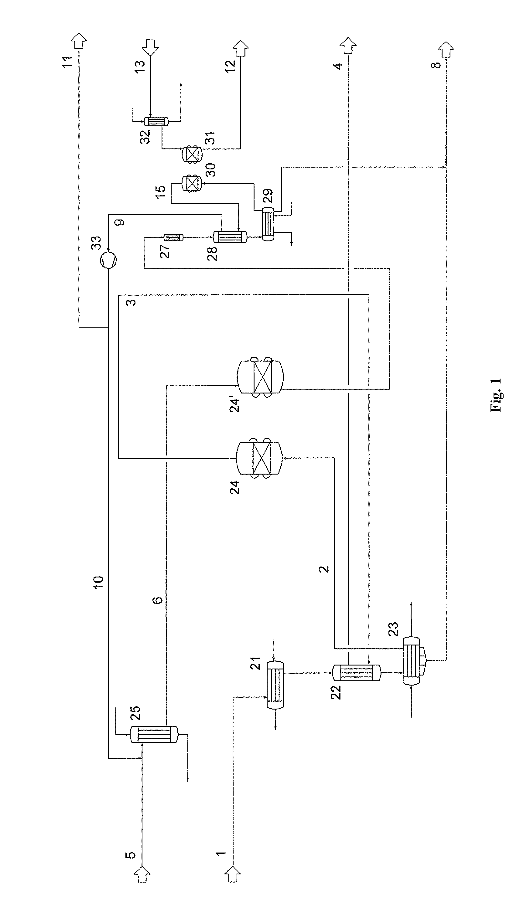
[0062]Referring to FIG. 1, a process in accordance with an embodiment of the present invention is depicted, which provides high purity of the regenerating gas, and hence a high degree of regeneration of the adsorber, while at the same time, the amount of inert gas consumed is minimal.

[0063]As is shown in FIG. 1, the regenerating gas stream is guided in a circuit in the process according to the invention, and the amount of inert gas consumed is thus minimized.

[0064]An initial crude gas stream 1 is precooled in a cooler 21 and passed through the recuperator 22 to provide a crude gas stream. In this example, the initial crude gas stream comprised a hydrogen chloride gas from a TDI production. Organic impurities such as chlorobenzene, hexachlorobenzene, and / or orthodichlorobenzene are condensed in the condenser 23 and discharged as stream 8.

[0065]The prepurified crude gas 2 is passed over an adsorber bed 24 of activated carbon, and the purified gas stream 3 of hydrogen chloride is passe...

example 2

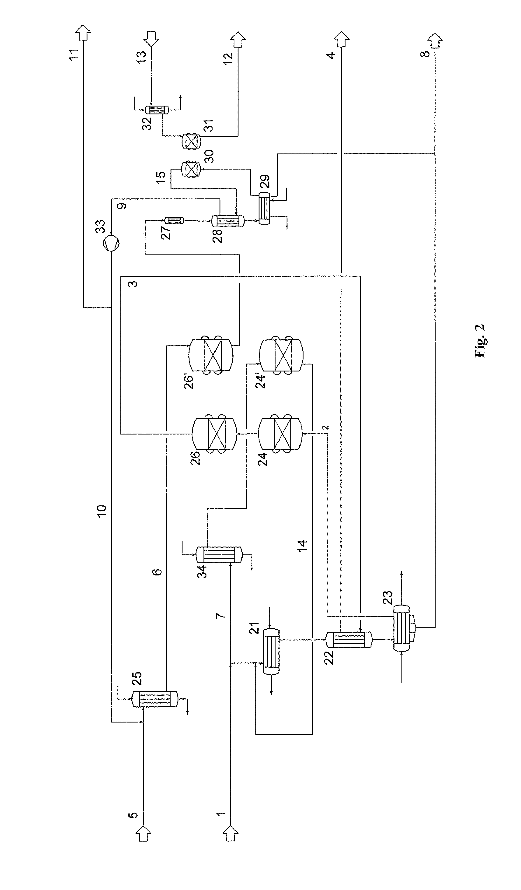
[0072]Referring to FIG. 2, an additional embodiment of a process according to the present invention for making a saving in terms of the inert gas used for the regeneration is depicted and includes using heated process gas for the partial regeneration of the adsorbers. This embodiment employs a two-stage, redundant adsorber unit 24, 26 or 24′, 26′.

[0073]In adsorption mode, the crude gas 1 here too passes through the cooling and condensation stages 21, 22 and 23 which have already been described above with reference to FIG. 1, and in which some of the organic components contained in the gas stream are removed. The prepurified crude gas 2 from stage 23 is fed to a two-stage adsorption 24, 26, where some or all of the remaining organic components are separated off.

[0074]The embodiment depicted in FIG. 2 employs a two-stage adsorption because in regeneration operation the first adsorption stage 24′ is only partially regenerated with the heated partial stream 7 of the crude gas, and the r...


PUM

PropertyMeasurementUnit
Temperatureaaaaaaaaaa

Abstract

Processes are described comprising: providing a crude gas stream having a temperature not exceeding 40° C., the crude gas stream comprising at least one organic impurity; condensing at least a portion of the at least one organic impurity from the crude gas stream at a temperature not exceeding 0° C. to form a prepurified gas stream; and subjecting (at least a portion, preferably substantially all, and more preferably the entirety, of) the prepurified gas stream to adsorption on a first adsorption medium to provide a purified gas stream; wherein the first adsorption medium is subjected to a regeneration comprising: (i) providing a circulating inert gas stream having a temperature of at least 100° C.; (ii) passing the circulating inert gas stream over the first adsorption medium to form an organic impurity-loaded inert gas stream; (iii) cooling the loaded inert gas stream to a temperature not exceeding 40° C.; (iv) condensing at least a portion of the organic impurity from the cooled, loaded inert gas stream to provide a prepurified circulating inert gas stream; subjecting (at least a portion, preferably substantially all, and more preferably the entirety, of) the prepurified circulating inert gas stream to adsorption on a second adsorption medium to provide a purified circulating inert gas stream; and recycling the purified circulating inert gas stream to the circulating inert gas stream.

Description

BACKGROUND OF THE INVENTION[0001]A process for the catalytic oxidation of HCl gas is described in European Patent No. EP 233 773 B1, in which a HCl gas contaminated with organic impurities such as benzene, chlorobenzene and the like is prepurified for use in a Deacon process (catalytic HCl oxidation by means of oxygen). In the prepurification described therein, activated carbon is used as the adsorber and is regenerated after use. It is further proposed to regenerate the adsorber at elevated temperatures or under reduced pressure and optionally using an inert gas.[0002]One disadvantage of such a process is that the production process and the HCl purification process must be interrupted for regeneration of the activated carbon bed. A further disadvantage of such a process is that the regeneration is conducted thermally or at reduced pressure, which is disadvantageous in terms of energy, or is carried out using an inert gas, which is expensive.[0003]Adsorptive separation to remove con...

Claims


Application Information

Patent Timeline
IPC IPC(8): B01D46/46
CPCB01D53/002B01D53/04B01D2253/102B01D2257/2064B01D2257/70B01D2257/7027B01D2259/4009C01B7/04C01B7/0718C01B7/0725Y02P20/129Y02P20/151Y02P20/20B01D5/00B01D53/00B01D53/02C01B7/07
Inventor BRETTSCHNEIDER, OLEWERNER, KNUDERWE, TORSTEN
Owner BAYER MATERIALSCIENCE AG
Learn More