
Protective circuit board and overcurrent protection device thereof

a protection device and circuit board technology, applied in secondary cell servicing/maintenance, electrochemical generators, batteries, etc., can solve the problems affecting mass production, etc., and achieve the effect of reducing manufacturing time and cost and facilitating mass production

Active Publication Date: 2008-10-16
POLYTRONICS TECH
View PDF5 Cites 16 Cited by
  • Summary
  • Abstract
  • Description
  • Claims
  • Application Information

AI Technical Summary

Benefits of technology

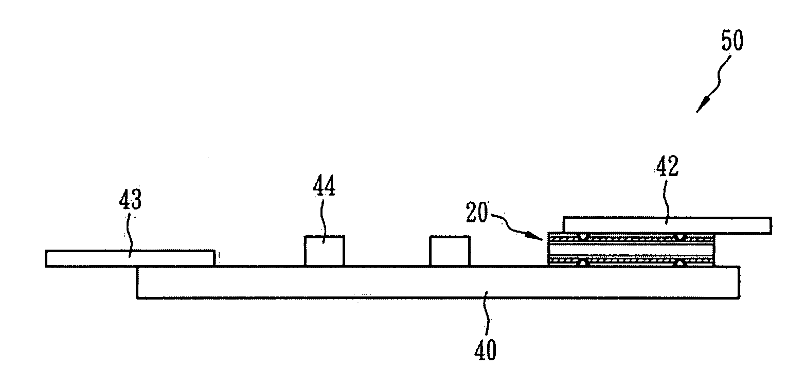
[0007]The present invention provides a protective circuit board and an over-current protection device, which can be applied to a PCM for a battery. The over-current protection device can be combined with the PCM or an external electrode plate by spot-welding, so as to facilitate mass production and therefore significantly reduce manufacturing time and cost.
[0009]The over-current protection device of the present invention can be subjected to spot-welding directly, so that it is not necessary to manually attach an electrode plate to the PTC device as required in the prior art, which makes the present invention more suitable for mass production. Therefore, the process can be simplified, the manufacture efficiency can be increased, and the over-current protection device is very flexible for subsequent manufacturing process.
[0011]Moreover, the over-current protection device can be secured to a surface of a PCM to form a protective circuit board with over-current protection function, which is very useful for manufacturing.

Problems solved by technology

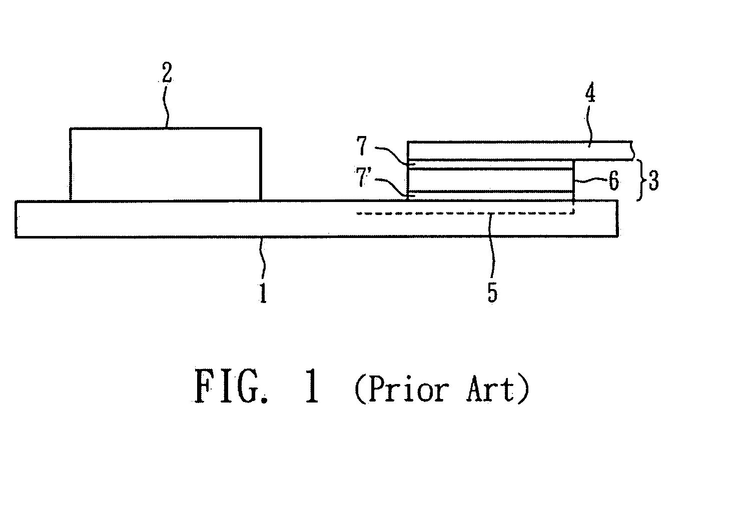
However, the nickel plate 4 is usually attached to the PTC device 3 manually, which is detrimental to mass production and cost reduction.

Method used


Image

  • Protective circuit board and overcurrent protection device thereof
  • Protective circuit board and overcurrent protection device thereof
  • Protective circuit board and overcurrent protection device thereof

Examples


Embodiment Construction

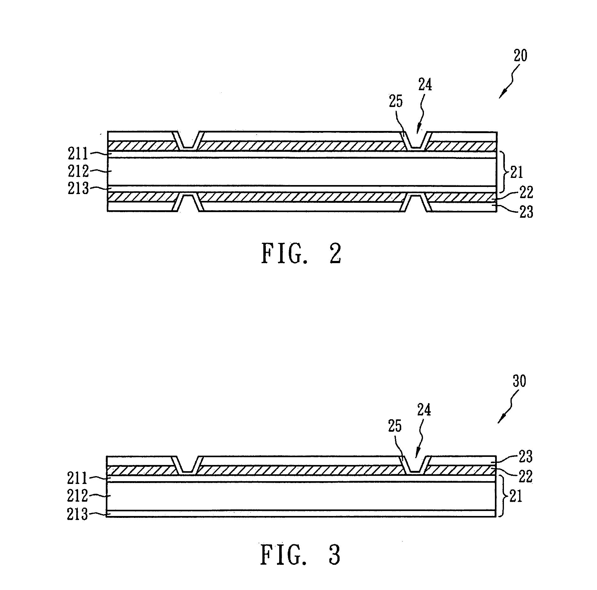
[0017]FIG. 2 illustrates an over-current protection device in accordance with an embodiment of the present invention. An over-current protection device 20 comprises a PTC device 21, insulation layers 22 and electrode layers 23. The PTC device 21 is a stack structure in which a PTC material layer 212 is laminated between metal electrode foils 211 and 213. The thickness of the metal electrode foil 211 or 213 is between 0.025 and 0.5 mm. The PTC material layer 212 comprises a crystalline polymer material mixed with conductive fillers. The insulation layers 22 and the electrode layers 23 are disposed on two sides of the PTC device 21. The insulation layers 22 are disposed on the surfaces of the PTC device 21, and electrode layers 23 are disposed on insulation layers 22. The thickness of the electrode layer 23 is between 0.025 and 0.5 mm.

[0018]When the PTC device 21, the insulation layers 22 and electrode layers 23 are combined, blind holes 24 penetrating through the electrode layers 23 ...


PUM


Abstract

The over-current protection device of the present invention can be used for over-current protection to PCM. The over-current protection device comprises a PTC device, at least one insulation layer; at least one electrode layer and at least one conductive channel. The insulation layer is placed on a surface of the PTC device, and the electrode layer is formed on the insulation layer afterwards. As a result, the insulation layer is between the electrode layer and the PTC device. The electrode layer serves as a surface of the over-current protection device. The conductive channel electrically connects the PTC device and the electrode layer. In an embodiment, the conductive channel is a blind hole penetrating through the electrode layer and the insulation layer and ending at the surface of the PTC device, and the surface of the blind hole is coated with a conductive layer to electrically connect the PTC device and the electrode layer.

Description

BACKGROUND OF THE INVENTION[0001](A) Field of the Invention[0002]The present invention relates to a protective circuit board and the over-current protection device thereof.[0003](B) Description of the Related Art[0004]Because the resistance of conductive materials having a positive temperature coefficient (PTC) characteristic is very sensitive to temperature variation, such materials can be used for current sensing devices, and have been widely applied to over-current protection devices or circuit devices. The resistance of PTC conductive material remains extremely low at normal temperature, so that the circuit or cell can operate normally. However, when an over-current or an over-temperature event occurs in the circuit or cell, the resistance will instantaneously increase to a high resistance state (e.g. at least above 104 ohms), which is the so-called trip. Therefore, the over-current will be eliminated so as to protect the cell or the circuit device.[0005]U.S. Pat. No. 6,713,210 ...

Claims


Application Information

Patent Timeline
Patent Type & Authority Applications(United States)
IPC IPC(8): H02H5/04H02H3/08
CPCH01C1/01H01C1/1406H01M2200/106H01M10/425H01M10/48H01C7/02Y02E60/10
Inventor YU, CHING HANWANG, DAVID SHAU CHEWCHEN, PAO HSUAN
Owner POLYTRONICS TECH
Learn More