System and method for receiving and decoding electromagnetic transmissions within a well

a technology of electromagnetic transmission and system, applied in the field of system and method for receiving and decoding electromagnetic transmission within a well, can solve the problem of limiting the overall applicability of the technique, and achieve the effect of improving signal strength, effectively communicating with and wirelessly interrogating sensors

a technology of electromagnetic transmission and system, applied in the field of system and method for receiving and decoding electromagnetic transmission within a well, can solve the problem of limiting the overall applicability of the technique, and achieve the effect of improving signal strength, effectively communicating with and wirelessly interrogating sensors

US20080253230A1Active Publication Date: 2008-10-16CHEVROU USA INC

Image

  • System and method for receiving and decoding electromagnetic transmissions within a well
  • System and method for receiving and decoding electromagnetic transmissions within a well
  • System and method for receiving and decoding electromagnetic transmissions within a well

Examples


Embodiment Construction

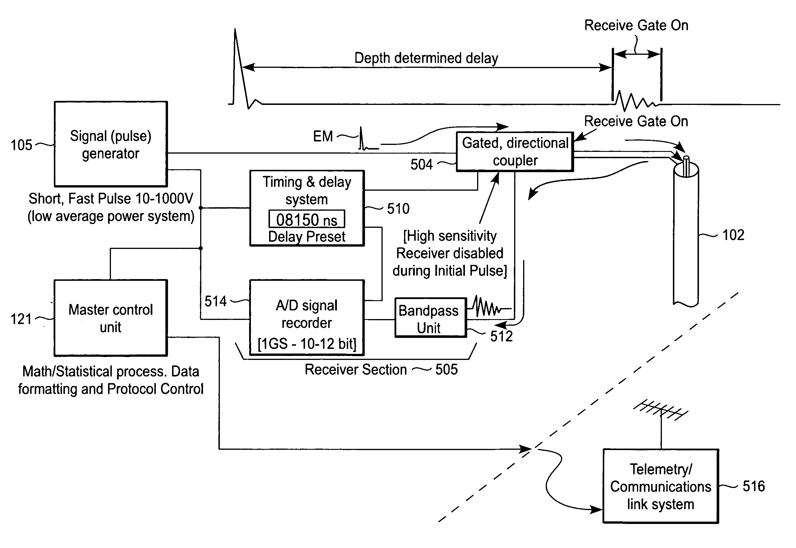
[0027]As mentioned above, the present invention utilizes an electromagnetic (EM) pulse to wirelessly interrogate one or more transducers (sensors) in a downhole environment. An EM pulse is a broadband, high-duration burst of electromagnetic energy. See FED-STD-1037C, ā€œTelecommunications: Glossary of Telecommunication Terms,ā€ GSA, Aug. 7, 1996. Such EM pulses differ markedly from the radiofrequency (RF) signals used in Briles et al., U.S. Pat. No. 6,766,141.

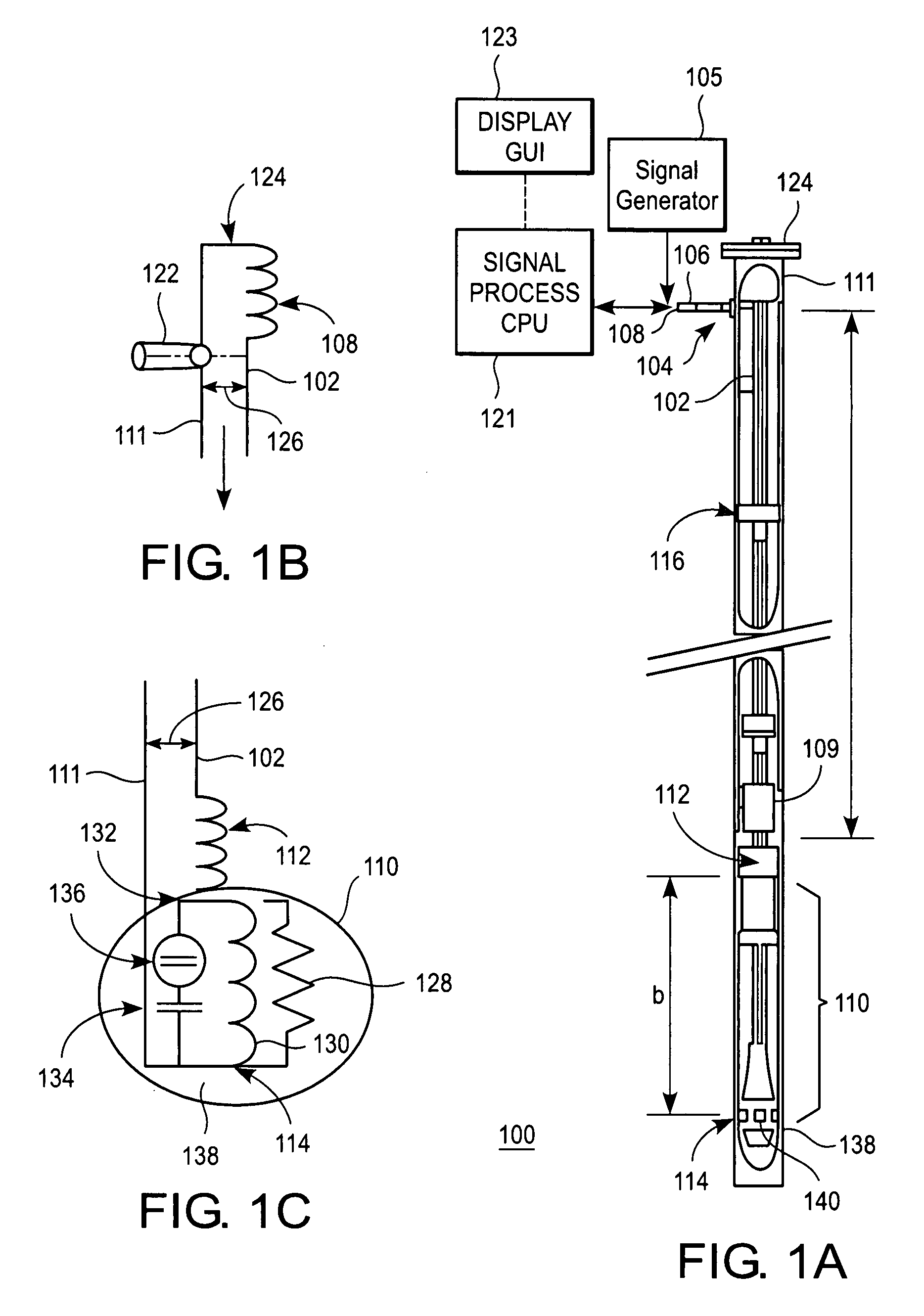
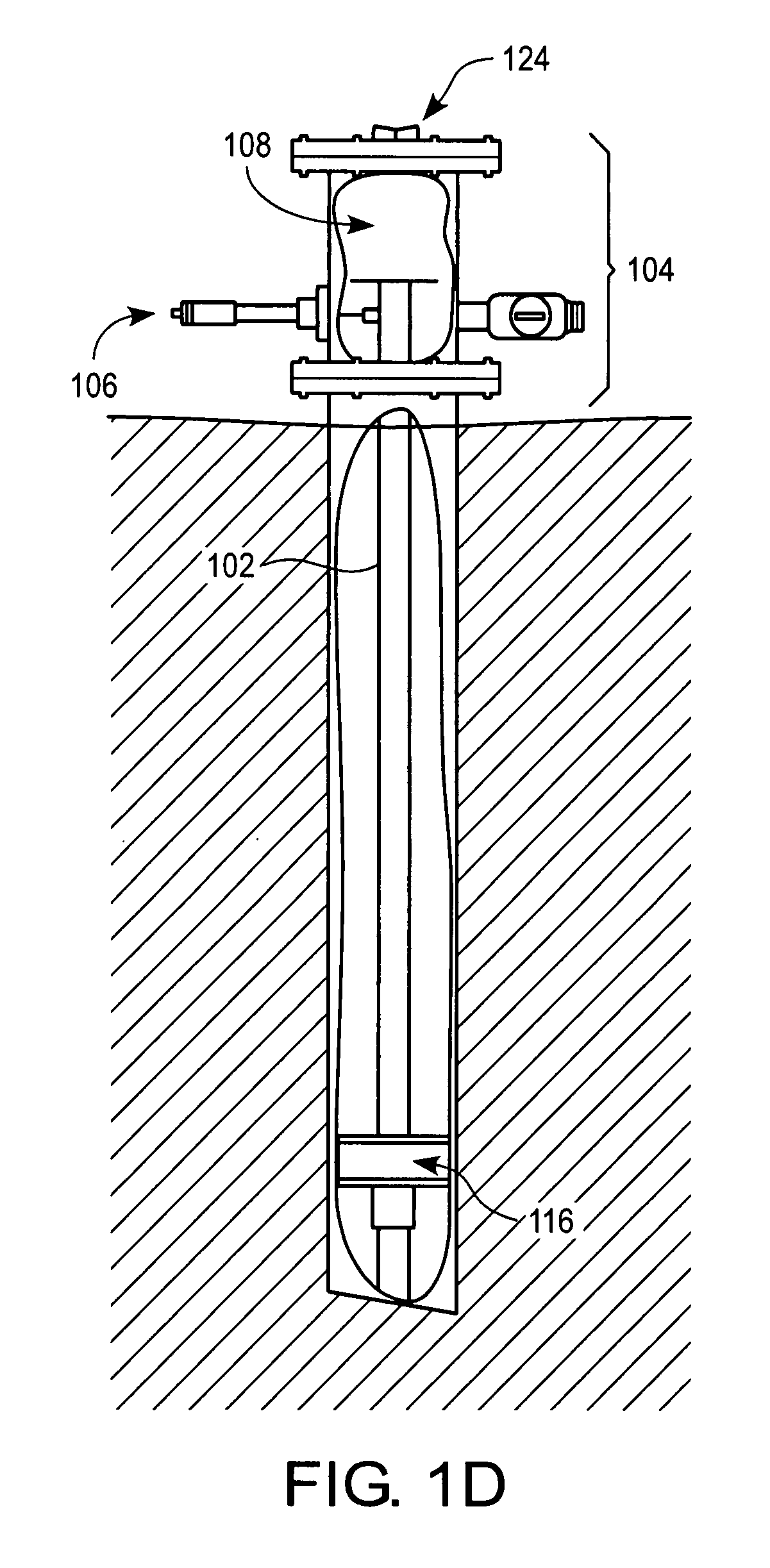
[0028]FIG. 1 shows an exemplary apparatus 100 for interrogating a downhole environment, in accordance with tsome embodiments of the present invention. Apparatus 100 is more fully described below.

[0029]As referenced herein, a downhole environment can be an area within or below the surface of a landform that includes a borehole and the area surrounding a borehole through which electromagnetic energy can be communicated. The borehole can be a cavity that can be located within or beneath a landform, and which can be characterized by v...


PUM


Abstract

Exemplary systems and methods are directed to transmission of electromagnetic (EM) pulses in a downhole environment, which is located below a surface of a landform. A sequence of EM energy pulses is generated from a signal generator located at the surface of the landform. The energy pulses are reflected at a ring frequency by one or more downhole transducers. The reflected energy pulse is received at a receiver, which is located at the surface, during a predetermined time interval. The receiver detects the received energy pulses through a time domain or frequency domain technique. The detected ring frequency is correlated to a parameter or condition of the downhole environment.

Description

BACKGROUND[0001]1. Field[0002]Methods and systems are disclosed for receiving and decoding electromagnetic-based information and its communication within a well.[0003]2. Background Information[0004]U.S. Pat. No. 6,766,141 (Briles et al.) discloses a system for remote downhole well telemetry. Telemetry communication is used for monitoring oil well conditions and recording instruments which are located in a vicinity of a bottom of a gas or oil recovery pipe.[0005]As described in U.S. Pat. No. 6,766,141, known telemetry systems include a radio frequency (RF) generator / receiver base station that communicates electrically with conductive piping located in a borehole. The RF frequency is characterized as being electromagnetic radiation between 3 Hz and 30 GHz. A downhole electronics module having a reflecting antenna receives a radiated carrier signal from the RF generator / receiver. The radiated carrier signal is then modulated and reflected, the modulation being responsive to downhole me...

Claims


Application Information

Patent Timeline
16 Oct 2008
Publication
US20080253230A1
IPC
G01V1/50
CPC
E21B47/122; G01V11/002; E21B47/13
Inventors
THOMPSON, M. CLARK; BECK, DAVID W.