Solar power for thermochemical production of hydrogen

a thermochemical and solar energy technology, applied in the direction of machines/engines, refrigeration machines, energy input, etc., can solve the problems of high plant capital costs, high plant availability, and net loss of total energy and pollution,

Inactive Publication Date: 2008-10-23
SOLARRESERVE TECH
View PDF13 Cites 36 Cited by
  • Summary
  • Abstract
  • Description
  • Claims
  • Application Information

AI Technical Summary

Problems solved by technology

However, steam methane reforming results in a net loss of total energy and the release of pollution.
While depletion of coal is not an immediate concern, the gasification of coal has other disadvantages, including: high plant capital costs, plant availability, coal mining, coal transportation, and various forms of pollution.

Method used


Image

  • Solar power for thermochemical production of hydrogen
  • Solar power for thermochemical production of hydrogen
  • Solar power for thermochemical production of hydrogen

Examples


Embodiment Construction

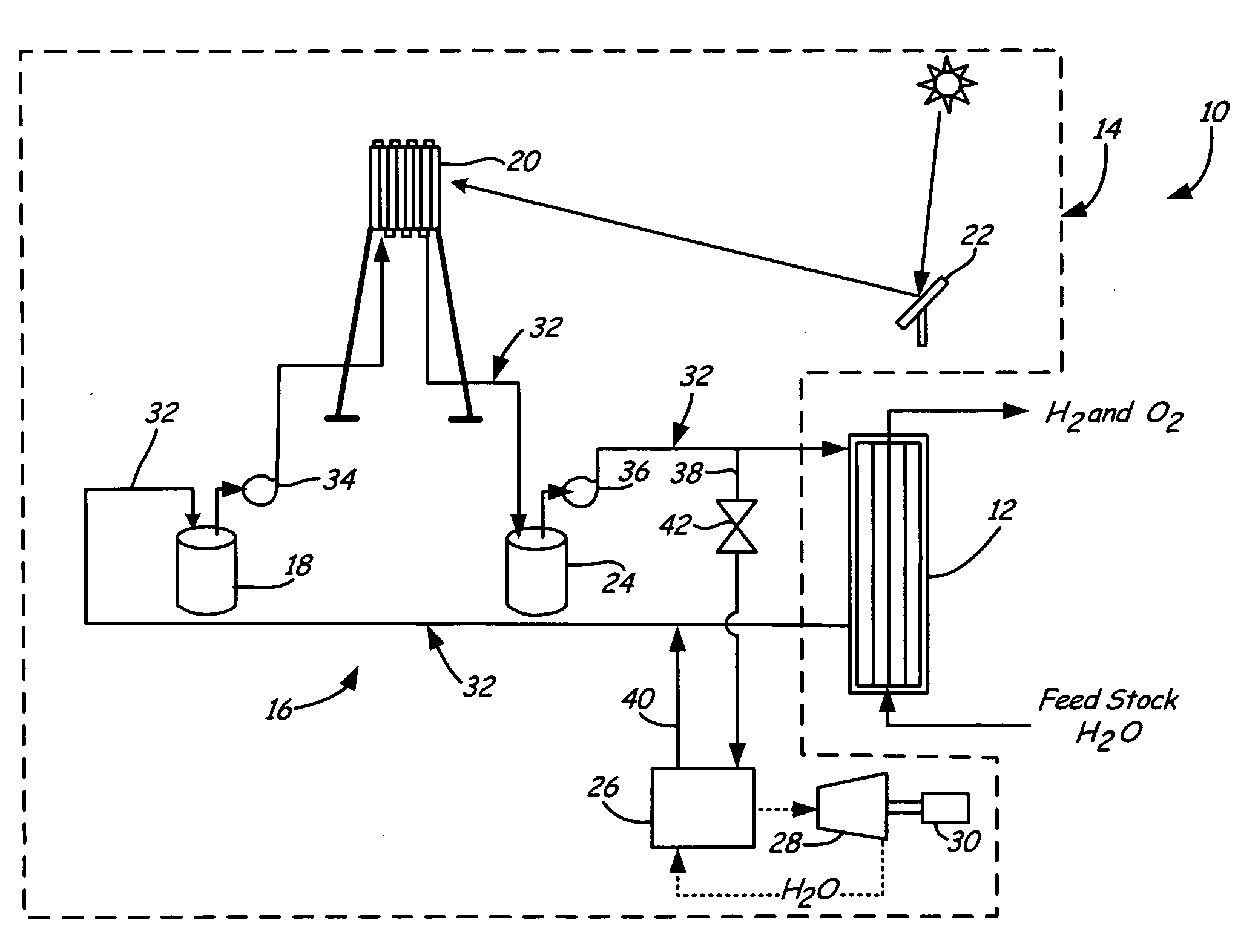
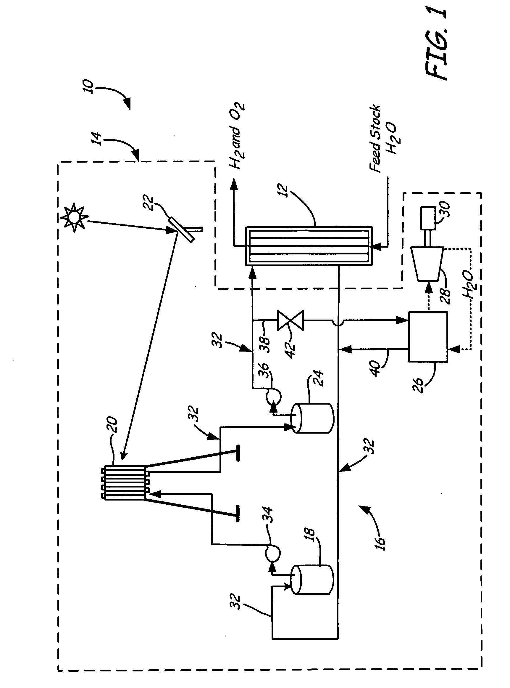
[0009]FIG. 1 shows a schematic of solar-powered hydrogen production system 10, which generally includes thermochemical system 12 and solar heating system 14. Thermochemical system 12 provides a low temperature process of producing hydrogen, eliminating the need for high temperature refractory materials and high concentrating solar thermal plant designs. Solar heating system 14 is capable of providing thermal and electrical energy to thermochemical system 12 up to 24 hours a day. The continuous use of thermochemical system 12 and solar heating system 14 in conjunction with one another allows for efficient use of thermochemical system 12 by avoiding restart problems and thermal transients. This increases the overall efficiency and asset utilization of solar-powered hydrogen production system 10, improving operating economics.

[0010]Thermochemical system 12 uses a copper chloride (CuCl) thermochemical cycle to produce hydrogen. The addition of several other steps allows for the producti...


PUM

PropertyMeasurementUnit
temperatureaaaaaaaaaa
thermal energyaaaaaaaaaa
electrical energyaaaaaaaaaa

Abstract

A solar-powered hydrogen production system includes a thermochemical system and solar heating system. The thermochemical system produces hydrogen. The solar heating system has a molten salt heat transfer medium for providing thermal energy to the thermochemical system.

Description

BACKGROUND OF THE INVENTION[0001]The present invention relates generally to hydrogen production systems. In particular, the invention relates to a hydrogen production system powered by a renewable energy source.[0002]There is a continuing demand for clean renewable energy sources due to the depletion of the Earth's supply of fossil fuels and concerns over their contribution to global warming. Hydrogen promises to be a clean fuel that can be produced by renewable energy as a fossil fuel replacement. Hydrogen can readily be used in many industrial applications, such as internal combustion engines with little engine modification, in fuel cells to generate electricity, or in power plants to generate electricity.[0003]Hydrogen is currently primarily produced from methane through steam methane reforming. However, steam methane reforming results in a net loss of total energy and the release of pollution. Another hydrogen production method uses coal in a gasification process. While depletio...

Claims


Application Information

Patent Timeline
Patent Type & Authority Applications(United States)
IPC IPC(8): B60K16/00C01B13/00F24S20/20F24S90/00
CPCC01B3/08C02F1/14F24J2/07F24J2/42F24J2/4649Y02E60/36Y02E10/41F28D2020/0047F24S80/20F24S90/00F24S20/20Y02E10/40Y02P20/133
Inventor LITWIN, ROBERT Z.PINKOWSKI, STANLEY M.
Owner SOLARRESERVE TECH
Why Eureka
Try Eureka