Lithographic apparatus and method

a technology of lithographic apparatus and lens array, which is applied in the field of lithographic apparatus and method, can solve the problems of wasting radiation beam parts, damage to lithographic apparatuses which are incident upon, and inability to use radiation beam parts,

Inactive Publication Date: 2008-10-23
ASML NETHERLANDS BV
View PDF34 Cites 42 Cited by
  • Summary
  • Abstract
  • Description
  • Claims
  • Application Information

AI Technical Summary

Benefits of technology

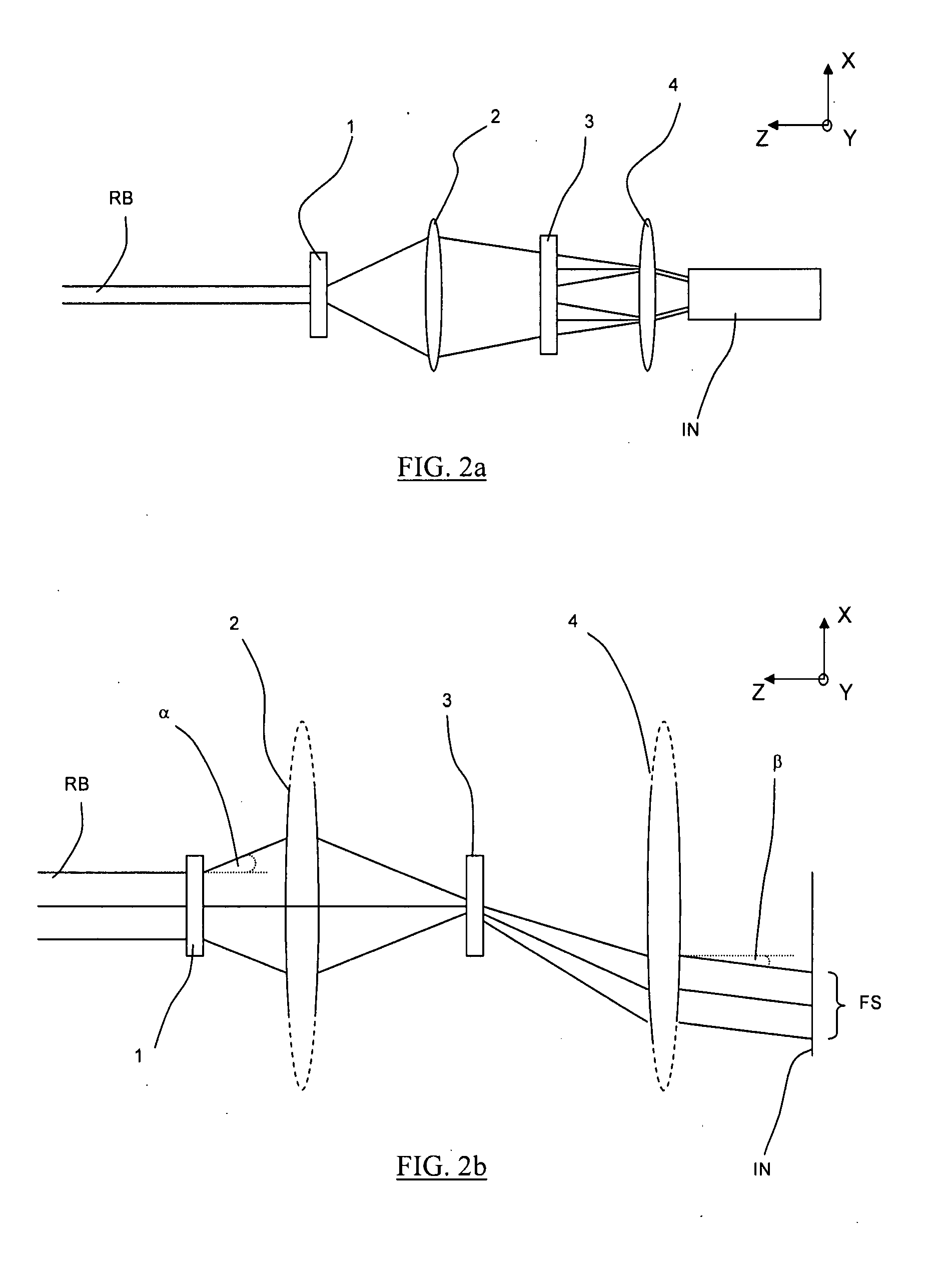
[0011]According to an embodiment of the present invention, there is provided a lithographic method including: providing a substrate; providing a beam of radiation using an illumination system; using a patterning device to impart the radiation beam with a pattern in its cross-section; and projecting the patterned radiation beam onto a target portion of the substrate, wherein the provision of the radiation beam using the illumination system includes: changing the field size of the radiation beam, the field position of the radiation beam or the uniformity of the radiation beam by exchanging a first spatial light modulator arranged to control the field size of the radiation beam, the field position of the radiation beam or the uniformity of the radiation beam with another spatial light modulator arranged to control the field size of the radiation beam, the field position of the radiation beam or the uniformity of the radiation beam, and applying a desired angular distribution to the radiation beam using a second spatial light modulator.
[0012]According to an embodiment of the present invention, there is provided a method of affecting properties of a radiation beam, the method including: changing the field size of the radiation beam, the field position of the radiation beam or the uniformity of the radiation beam by e...

Problems solved by technology

In a conventional lithographic apparatus, the radiation beam provided by a radiation source may be so intense (for example, due to the field size being so small) that, unless it is expanded using, for example, an array of small lenses, it may damage parts of the lithograph...

Method used


Image

  • Lithographic apparatus and method
  • Lithographic apparatus and method
  • Lithographic apparatus and method

Examples


Embodiment Construction

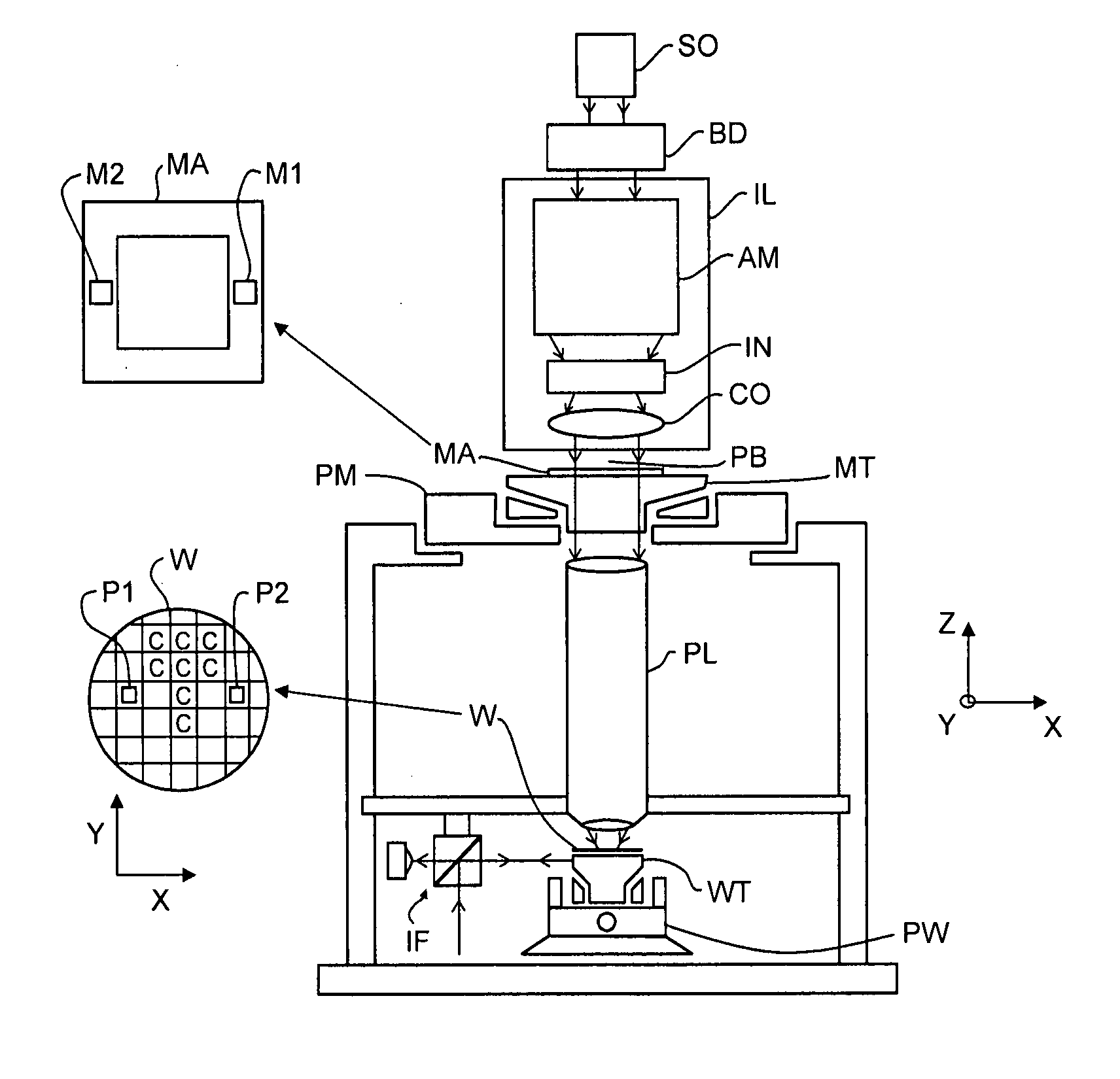
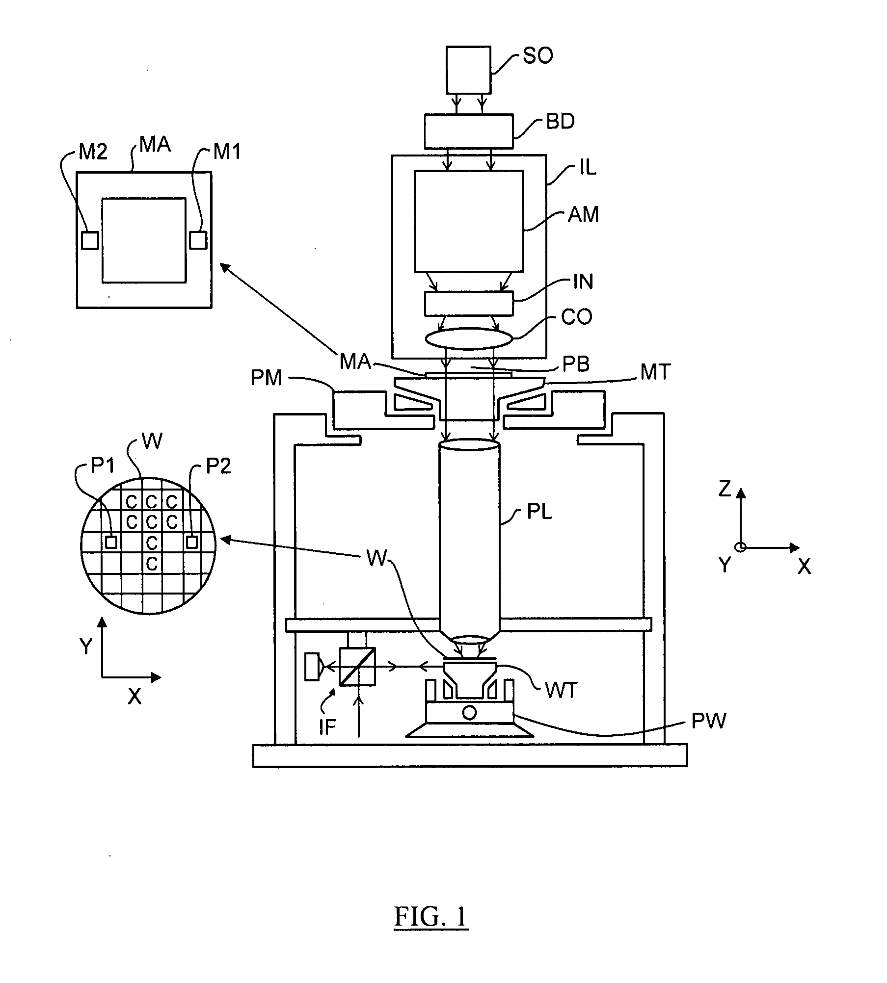
[0019]Although specific reference may be made in this text to the use of lithographic apparatus in the manufacture of ICs, it should be understood that the lithographic apparatus described herein may have other applications, such as the manufacture of integrated optical systems, guidance and detection patterns for magnetic domain memories, liquid-crystal displays (LCDs), thin-film magnetic heads, etc. The skilled artisan will appreciate that, in the context of such alternative applications, any use of the terms “wafer” or “die” herein may be considered as synonymous with the more general terms “substrate” or “target portion”, respectively. The substrate referred to herein may be processed, before or after exposure, in for example a track (a tool that typically applies a layer of resist to a substrate and develops the exposed resist) or a metrology or inspection tool. Where applicable, the disclosure herein may be applied to such and other substrate processing tools. Further, the sub...


PUM


Abstract

A lithographic apparatus includes an illumination system to provide a beam of radiation; a support structure to support a patterning device, the patterning device serving to impart the radiation beam with a pattern in its cross-section; a substrate table to hold a substrate; and a projection system to project the patterned radiation beam onto a target portion of the substrate. The illumination system includes a first spatial light modulator including a first array of individually controllable elements controllable to control the field size of the radiation beam, the field position of the radiation beam or the uniformity of the radiation beam, and a second spatial light modulator arranged to apply a desired angular distribution to the radiation beam.

Description

FIELD[0001]The present invention relates to a lithographic apparatus and method.BACKGROUND[0002]A lithographic apparatus is a machine that applies a desired pattern onto a target portion of a substrate. Lithographic apparatus can be used, for example, in the manufacture of integrated circuits (ICs). In that circumstance, a patterning device, which is alternatively referred to as a mask or a reticle, may be used to generate a circuit pattern corresponding to an individual layer of the IC, and this pattern can be imaged onto a target portion (e.g. including part of, one or several dies) on a substrate (e.g. a silicon wafer) that has a layer of radiation-sensitive material (resist). In general, a single substrate will contain a network of adjacent target portions that are successively exposed. Known lithographic apparatus include so-called steppers, in which each target portion is irradiated by exposing an entire pattern onto the target portion at once, and so-called scanners, in which...

Claims


Application Information

Patent Timeline
IPC IPC(8): G03B27/54
CPCG03F7/70083G03F7/70116G03F7/70291
Inventor DIERICHS, MARCEL MATHIJS THEODORE MARIE
Owner ASML NETHERLANDS BV
Why Eureka
Try Eureka