Control apparatus for hybrid vehicle drive system

a control apparatus and hybrid technology, applied in the direction of electric propulsion mounting, machines/engines, electric propulsion mounting, etc., can solve the problems of deteriorating the vehicle driving comfort as felt by the vehicle operator, control apparatus, shifting shock generation, etc., to improve the durability of the differential mechanism, the operation speed of the engine can be raised, and the operating speed of the second electric motor can be lowered.

Active Publication Date: 2008-10-23
TOYOTA JIDOSHA KK
View PDF2 Cites 28 Cited by
  • Summary
  • Abstract
  • Description
  • Claims
  • Application Information

AI Technical Summary

Benefits of technology

[0016]Preferably, the differential mechanism includes a coupling device operable to transmit a drive force from the second electric motor to the engine, and the engine-speed-rise control portion is configured to raise the operating speed of the engine by engaging the engaging device and operating the second electric motor. In this case, the operating speed of the second electric motor can be lowered where the engine speed can be raised to the value not lower than the predetermined engine starting speed even when the operating speed of the second electric motor is lowered. Accordingly, the durability of the differential mechanism is improved.

Problems solved by technology

Further, a shifting shock may be generated upon an engaging action of a coupling device of an automatic transmission which takes place to perform a shifting action.
If the engine-staring shock and the shifting shock overlap each other, the vehicle operator feels a large amount of shock due to the overlap, which deteriorates a vehicle driving comfort as felt by the vehicle operator.
However, the control apparatus suffers from some problems arising from its control arrangement to implement one of the switching operation of the shifting state of the continuously-variable transmission portion and the starting operation of the engine, prior to the other operation if these two operations would otherwise overlap each other.
If the switching operation of the shifting state is implemented prior to the engine starting operation, for example, the engine speed is raised and started only after completion of the switching operation of the shifting state of the continuously-variable transmission portion which takes a relatively long time.
In this case, therefore, the switching operation is delayed with respect to a moment of an operation of the vehicle operator to switch the shifting state of the continuously-variable transmission portion, and the rise of the vehicle drive torque generated by the drive system tends to be delayed.

Method used


Image

  • Control apparatus for hybrid vehicle drive system
  • Control apparatus for hybrid vehicle drive system
  • Control apparatus for hybrid vehicle drive system

Examples


Embodiment Construction

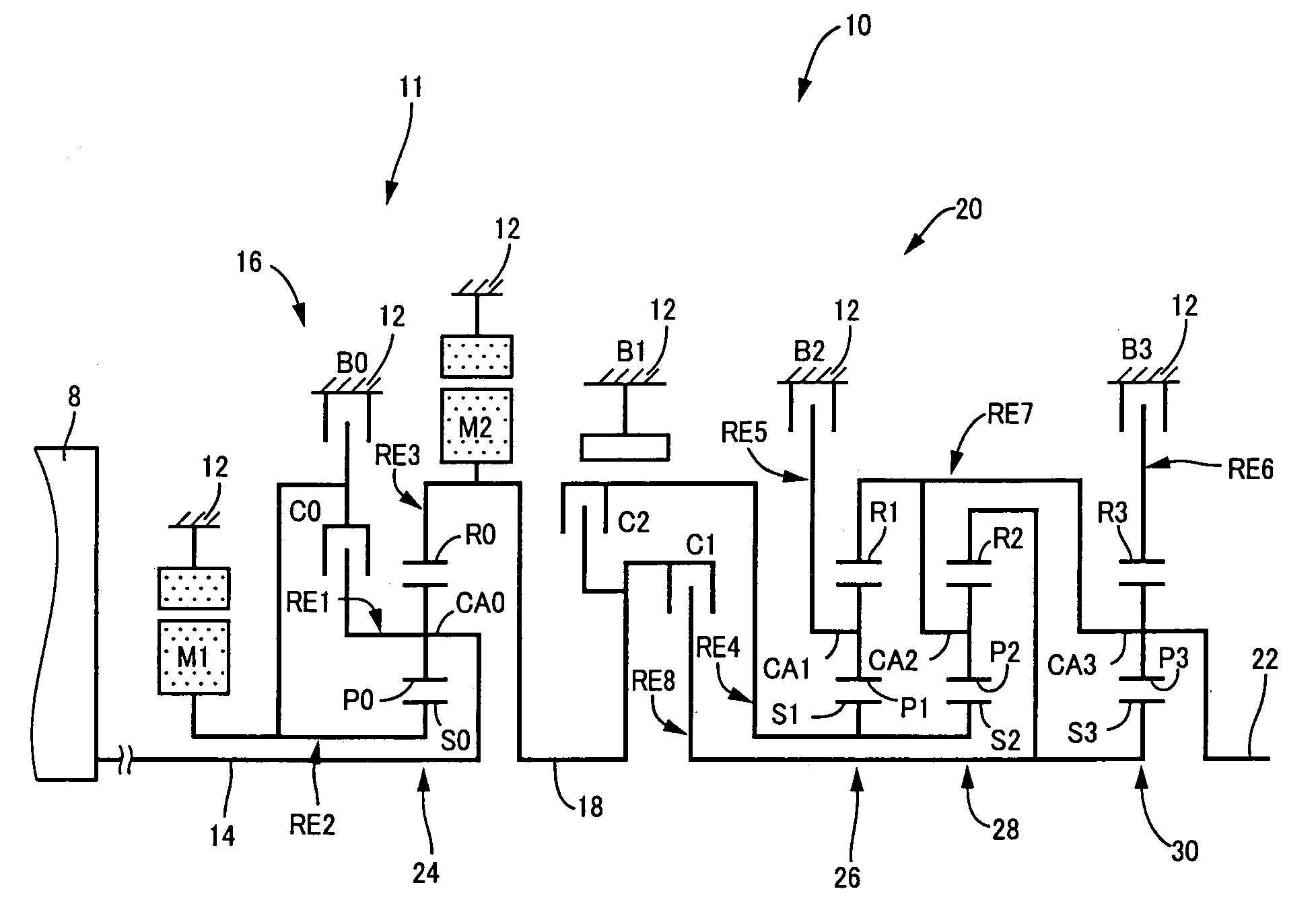
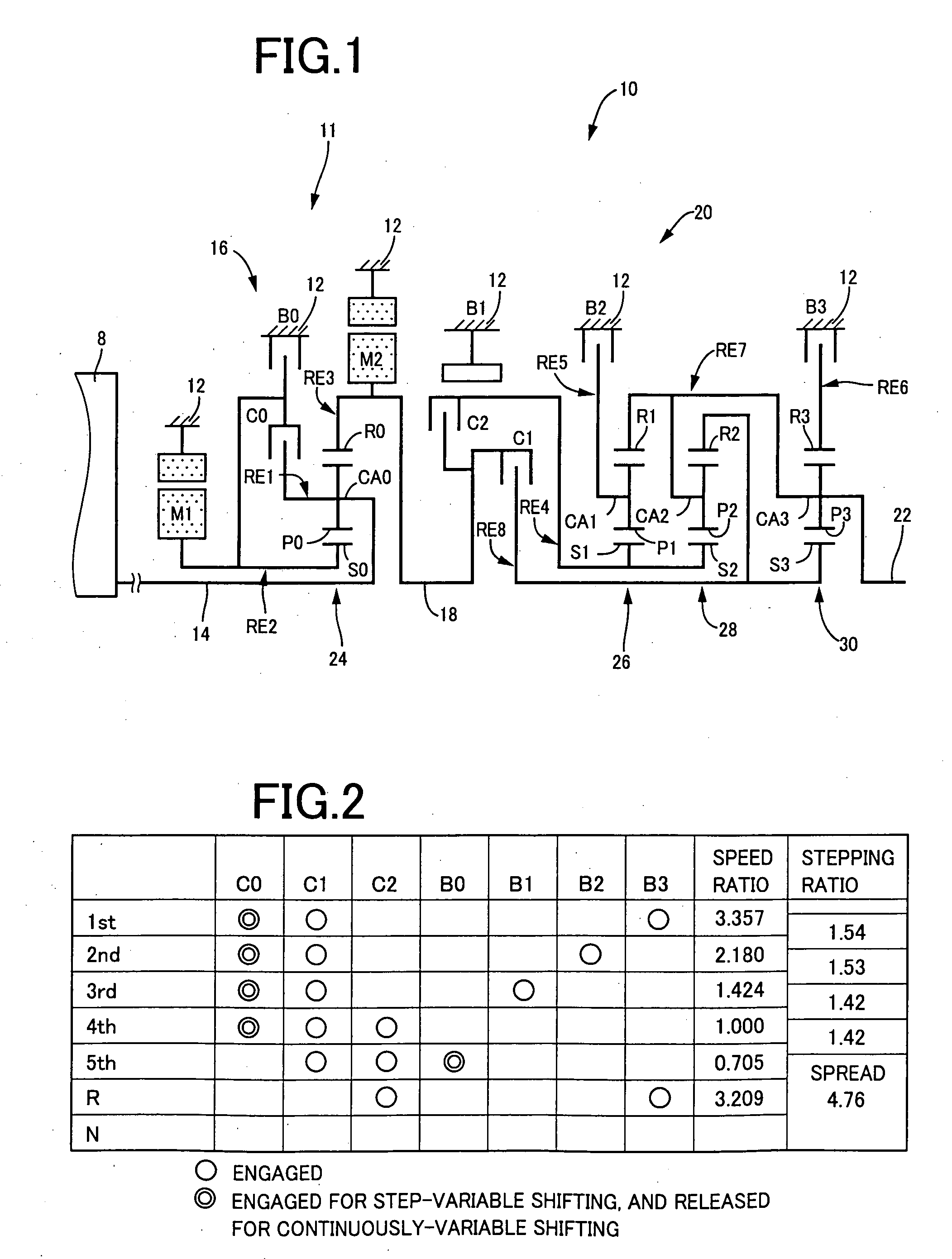
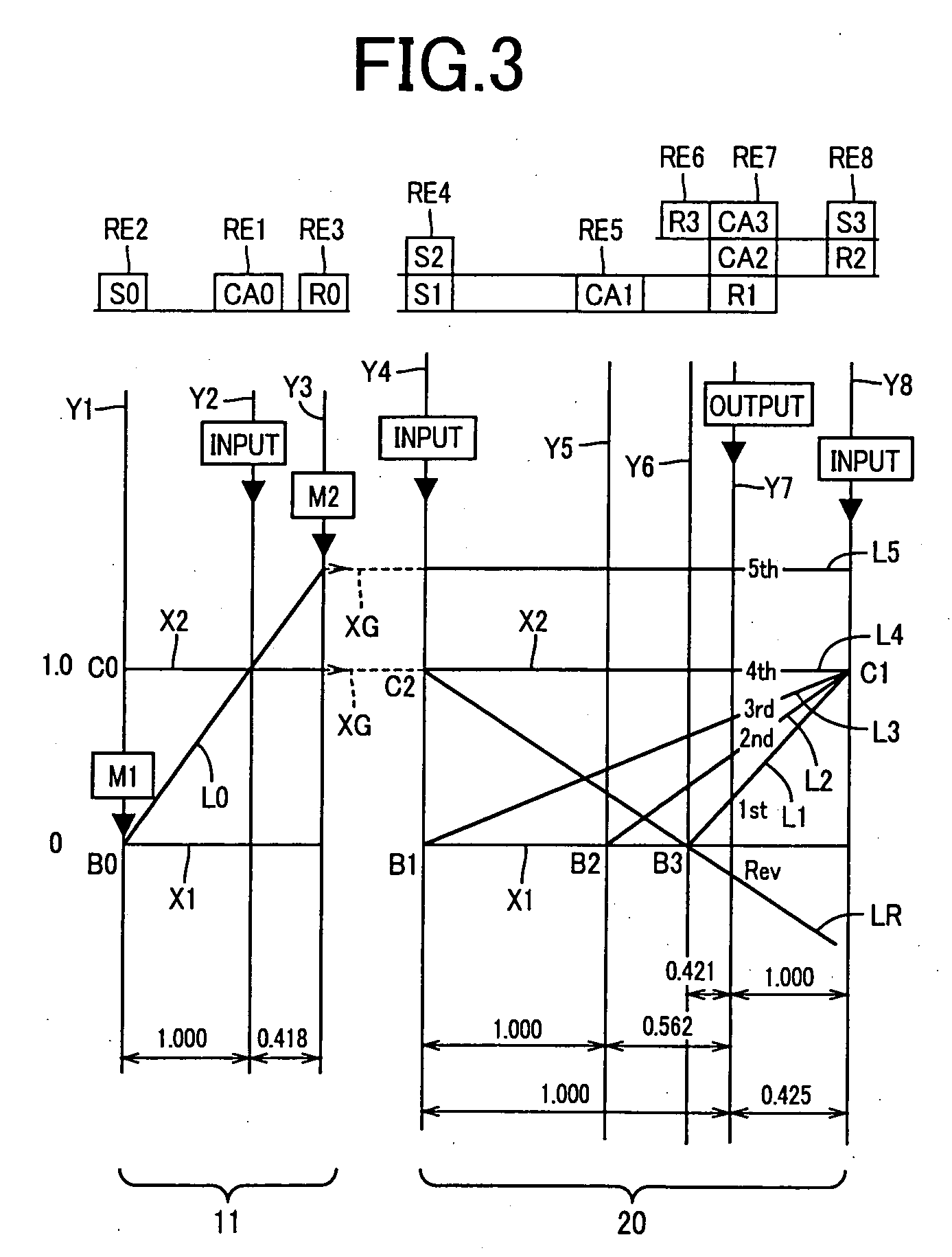
[0031]Referring to the schematic view of FIG. 1, there is shown a transmission mechanism 10 constituting a part of a drive system for a hybrid vehicle, which drive system is controlled by a control apparatus according to one embodiment of this invention. In FIG. 1, the transmission mechanism 10 includes: an input rotary member in the form of an input shaft 14; a differential portion 11 connected to the input shaft 14 either directly, or indirectly via a pulsation absorbing damper (vibration damping device) not shown; a step-variable or multiple-step transmission portion in the form of an automatic transmission portion 20 disposed between the differential portion 11 and drive wheels 38 of the vehicle, and connected in series via a power transmitting member 18 (power transmitting shaft) to the differential portion 11 and the drive wheels 38; and an output rotary member in the form of an output shaft 22 connected to the automatic transmission portion 20. The input shaft 12, differentia...


PUM


Abstract

A control apparatus for a drive system of a hybrid vehicle including (a) an engine, (b) an electrically controlled differential portion which has a first electric motor, and a differential mechanism operatively connected to the engine and the first electric motor and a differential state of which is controlled by controlling an operating state of the first electric motor, (c) a mechanical transmission portion constituting a part of a power transmitting path, and (d) a second electric motor connected to a power transmitting path between the electrically controlled differential portion and a drive wheel of the hybrid vehicle, the control apparatus including a control portion which is operable when a terminal portion of a shifting action of the mechanical transmission portion and a starting operation of the engine overlap each other, the control portion being configured to implement one of the shifting action and the starting operation prior to the other.

Description

[0001]The present application claims priority from Japanese Patent Application No. 2007-112320 filed on Apr. 20, 2007, the disclosure of which is herein incorporated by reference in its entirety.BACKGROUND OF THE INVENTION[0002]1. Field of the Invention[0003]The present invention relates in general to a control apparatus for a vehicular drive system, and more particularly to a control apparatus for a hybrid vehicle drive system including an internal combustion engine and an electric motor as vehicle drive power sources, which control apparatus is arranged to reduce a shock generated upon starting of the engine when a vehicle drive mode is changed from a motor drive mode to an engine drive mode.[0004]2. Discussion of Prior Art[0005]In a hybrid vehicle drive system as described above, an engine-starting shock may be generated upon starting of the engine when the vehicle drive mode is changed from the motor drive mode using the electric motor as the vehicle drive power source, to the e...

Claims


Application Information

Patent Timeline
Patent Type & Authority Applications(United States)
IPC IPC(8): B60W10/08B60K6/445B60K6/547B60L50/16B60W10/04B60W10/06B60W10/10B60W10/11B60W20/00F02D29/00F02D29/02
CPCB60K1/02Y10T477/23B60K6/40B60K6/445B60K6/547B60L2240/486B60W10/06B60W10/08B60W10/115B60W20/00B60W30/19F16H2037/0873Y02T10/56Y02T10/6286Y02T10/6239Y10T477/26B60K6/365Y02T10/84Y02T10/40Y02T10/62B60W2510/081B60W20/15
Inventor TABATA, ATSUSHIMATSUBARA, TOORUSHIBATA, HIROYUKIKUMAZAKI, KENTA
Owner TOYOTA JIDOSHA KK
Why Eureka
Try Eureka