
Method for improving efficiency in heating and cooling systems

a technology for hvac systems and efficiency improvement, applied in space heating and ventilation control systems, domestic cooling systems, lighting and heating apparatus, etc., can solve problems such as the implementation of user's actions is far easier, and achieve the effect of improving efficiency in hvac systems and increasing the operational efficiency of hvac systems

Inactive Publication Date: 2008-10-30
LIU MINGSHENG
View PDF10 Cites 22 Cited by
  • Summary
  • Abstract
  • Description
  • Claims
  • Application Information

AI Technical Summary

Benefits of technology

[0014]The present invention provides a method for improving efficiency in HVAC systems, the HVAC system having at least one of a fan and a pump, a motor for driving the pump, at least one air handling unit (AHU), and a heating / cooling system, the method comprising the steps of providing speed and pressure monitoring devices for monitoring and measuring the operational speed (OS) and the head pressure (HR) of the at least one of a fan and a pump and providing a flow rate monitoring device operatively associated with the at least one of a fan and a pump for monitoring and measuring the fluid flow rate (Q) for fluid flowing through the at least one of a fan and a pump. The OS, HR and Q for the at least one of a fan and a pump is then periodically obtained from the speed and pressure monitoring devices and the flow rate monitoring device, and by utilizing those readings, the operating S-value of the HVAC system is obtained by applying the formula: S-value=HR / (QR)2, thereby obtaining a measurable single value representative of the overall efficiency of the HVAC system. The operating S-value is then utilized to optimize operation of the at least one of a fan and a pump by adjusting the operational speed (OS) of the at least one of a fan and a pump such that HR / (Q)2 approaches the S-value set point of the HVAC system thereby increasing the operational efficiency of the HVAC system.
[0015]The present invention thus provides a substantial improvement over those systems and methods found in the prior art which are designed to provide for adjustment to HVAC systems for increasing efficiency. Specifically, because the method of the present invention does not require use of the remote pressure sensor already installed in the HVAC system in order to determine the most efficient operating speed for the pump or fan, it is not necessary for a user of the present invention to determine the location of the originally installed pressure sensor, determine if it is working correctly, and provide preventive maintenance to maintain the pressure sensor in its properly operating condition. Furthermore, because the system and method of the present invention generally reduces efficiency determinations to the proper operation of the fan or pump in connection with the HVAC system, it is far easier for a user to implement the method of the present invention as compared to those intricate and failure-prone systems and methods found in the prior art. Finally, because the present invention is usable not only with HVAC systems, but with any cooling or heating system which includes a fan or pump for driving fluid through the system, it may be adapted and used with many industrial chilling or heating systems which bear little if any resemblance to HVAC systems yet, because they include a pump or fan which can be controlled by an implementation of the present invention to increase efficiency, improvement in the efficiency of those industrial systems may be achieved through implementation of the present invention.
[0016]In the preferred embodiment, the proposed S-method will provide optimal and reliable fan and pump control, which will:
[0017]1. Maximize the fan / pump efficiency and save electrical energy consumption.

Problems solved by technology

Furthermore, because the system and method of the present invention generally reduces efficiency determinations to the proper operation of the fan or pump in connection with the HVAC system, it is far easier for a user to implement the method of the present invention as compared to those intricate and failure-prone systems and methods found in the prior art.

Method used


Image

  • Method for improving efficiency in heating and cooling systems
  • Method for improving efficiency in heating and cooling systems
  • Method for improving efficiency in heating and cooling systems

Examples


Embodiment Construction

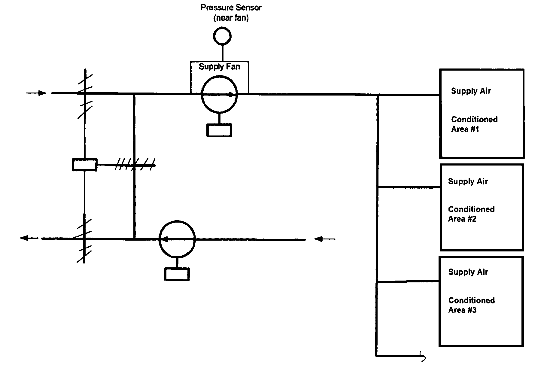
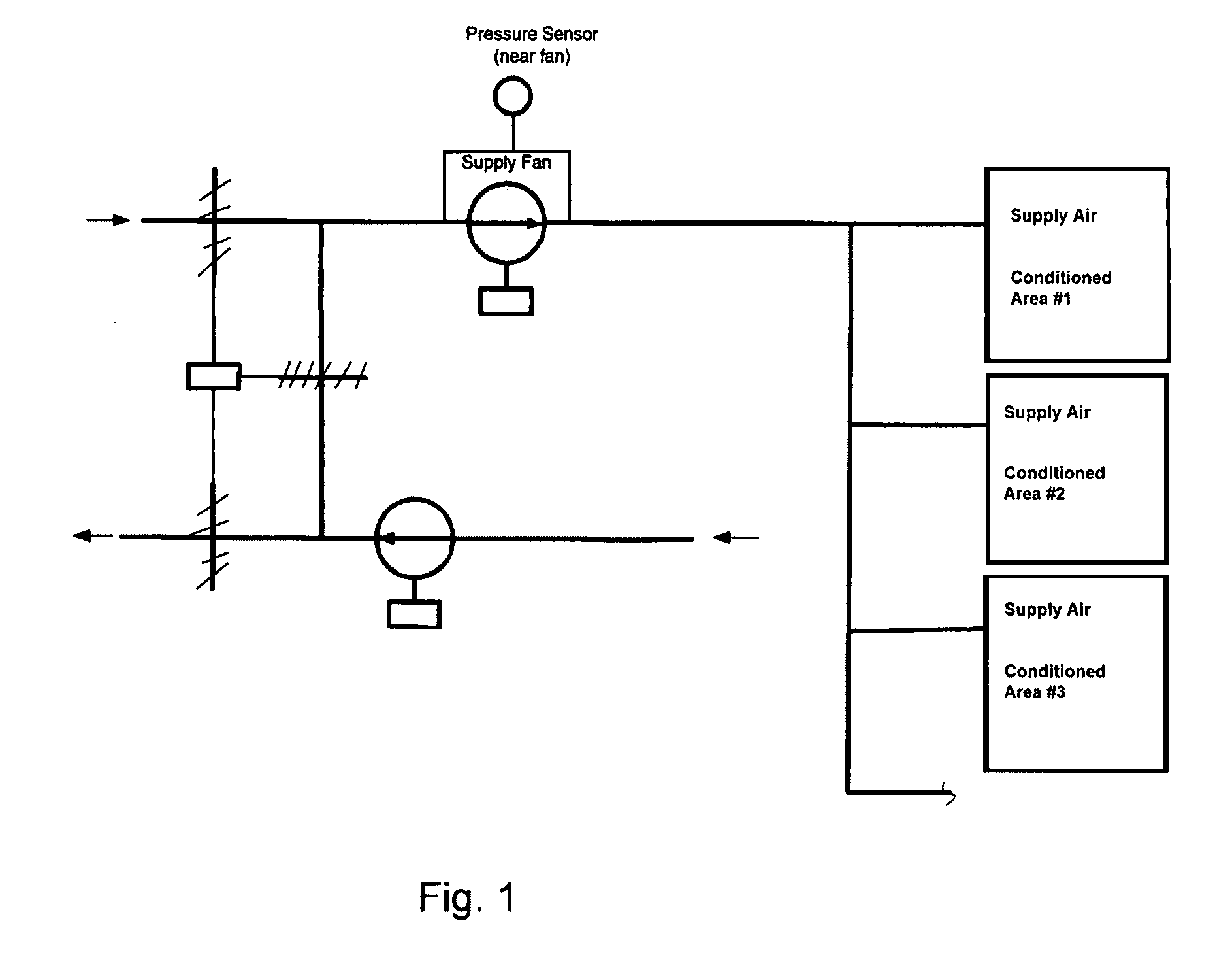
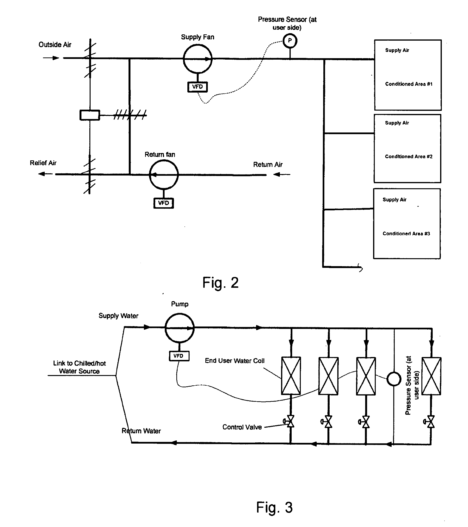
[0026]The S-value determination method is an intelligent control algorithm / system for optimally controlling fan / pump speed in heating ventilation and air-conditioning (HVAC) systems, such as those shown in FIG. 1, and in industrial chilling and heating systems having fans and / or pumps therein. This method intelligently modulates the fan (pump) speed to satisfy the desired flow, to maximize the energy system efficiency and to warrant stable end user device control. This method can be applied to variable air or water volume systems in HVAC systems for fan and pump speed control, and to industrial processes as well. FIG. 1 presents the schematic diagram of the S-value determination method, and in the preferred embodiment, the present invention would include the following sensors or signal sources: A differential pressure sensor or signal source is connected to the fan / pump to measure the fan head or pump head pressure, and a fluid flow meter is provided in the system to measure fan air...


PUM


Abstract

A method for improving efficiency in heating and cooling systems which includes the steps of providing speed and pressure monitoring devices for monitoring and measuring the operational speed (OS) and the head (HR) of the fan or pump and providing a flow rate monitoring device for monitoring and measuring the fluid flow rate (Q) for fluid flowing through the fan or pump. The OS, HR and Q for the fan or pump would be periodically obtained from the speed and pressure monitoring devices and the flow rate monitoring device, and the operating S-value of the heating and cooling system would be determined by applying the formula S-value=HR / (QR)2, thereby obtaining a measurable single value representative of the overall efficiency of the heating and cooling system.

Description

BACKGROUND OF THE INVENTION[0001]1. Technical Field[0002]The present invention relates generally to systems and methods for improving the efficiency of HVAC systems and, more particularly, to a method for improving efficiency in HVAC systems which includes the steps of providing speed and pressure monitoring devices for monitoring and measuring the operational speed and head pressure of the fan or pump of the air or water-based system, providing a fluid flow rate monitoring device which will measure the fluid and flow rate of fluid flowing through the fan or pump, periodically obtaining the operational speed, head pressure, and fluid flow rate from the monitoring devices, determining the S-value of the HVAC system by applying the formula H / Q squared and applying the S-value to optimize operation of the fan or pump by adjusting the operational speed such that the measured S-value approaches the set point S-value representing optimum flow efficiency.[0003]2. Description of the Prior A...

Claims


Application Information

Patent Timeline
IPC IPC(8): F25D17/00
CPCF24F11/0079F24F11/008F24F2011/0043F24F2011/0075Y02B30/746F24F2140/12F24F11/46F24F11/77F24F11/83Y02B30/70F24F11/85F24F11/84
Inventor LIU, MINGSHENG
Owner LIU MINGSHENG
Learn More