Radiation source

a radiation source and source technology, applied in the direction of pulse generation by logic circuits, pulse automatic control, pulse technique, etc., can solve the problems of further reducing power delivered, insertion loss and noise, adding to the cost, etc., and achieve the effect of easy and cheap phase shift control

Active Publication Date: 2008-10-30
CITY UNIVERSITY OF HONG KONG
View PDF15 Cites 31 Cited by
  • Summary
  • Abstract
  • Description
  • Claims
  • Application Information

AI Technical Summary

Benefits of technology

[0007]Accordingly, at its most general, the present invention proposes altering the signal phase indirectly by changing the phase of the phased locked loop's reference signal. Preferably the reference signal has a lower frequency than the output signal. As the reference signal usually has much lower frequency than the output signal

Problems solved by technology

Furthermore power dividers tend to be complicated and lossy and thus add to the expense and further decrease the power delivered.
Secondly, as the output signal itself passes

Method used


Image

  • Radiation source
  • Radiation source
  • Radiation source

Examples


Embodiment Construction

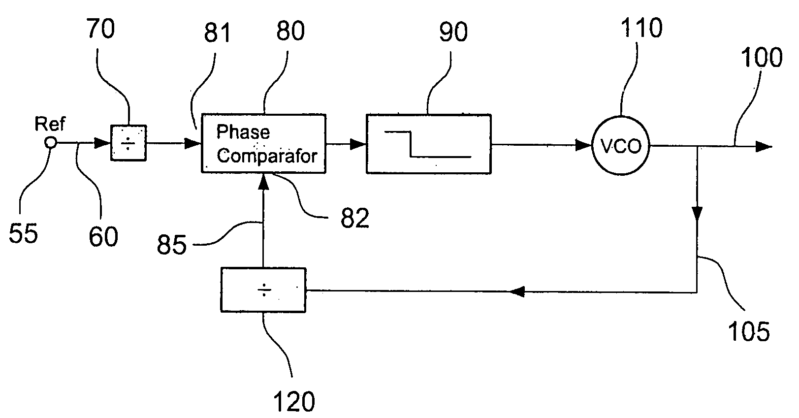
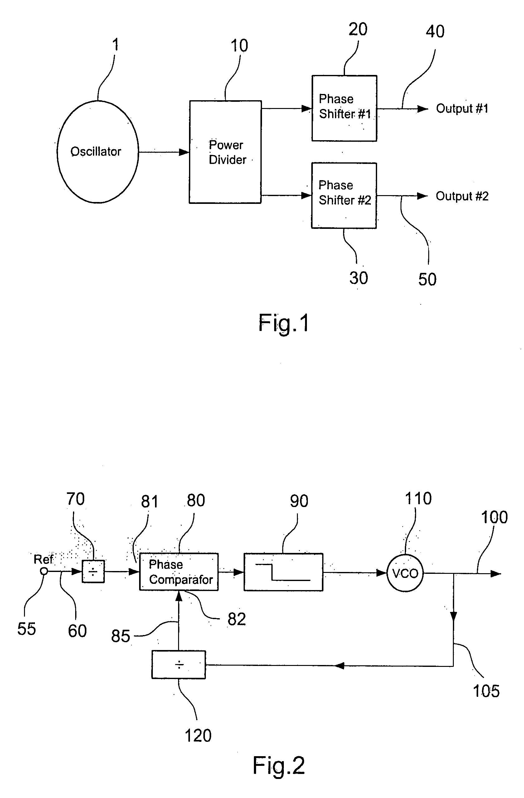
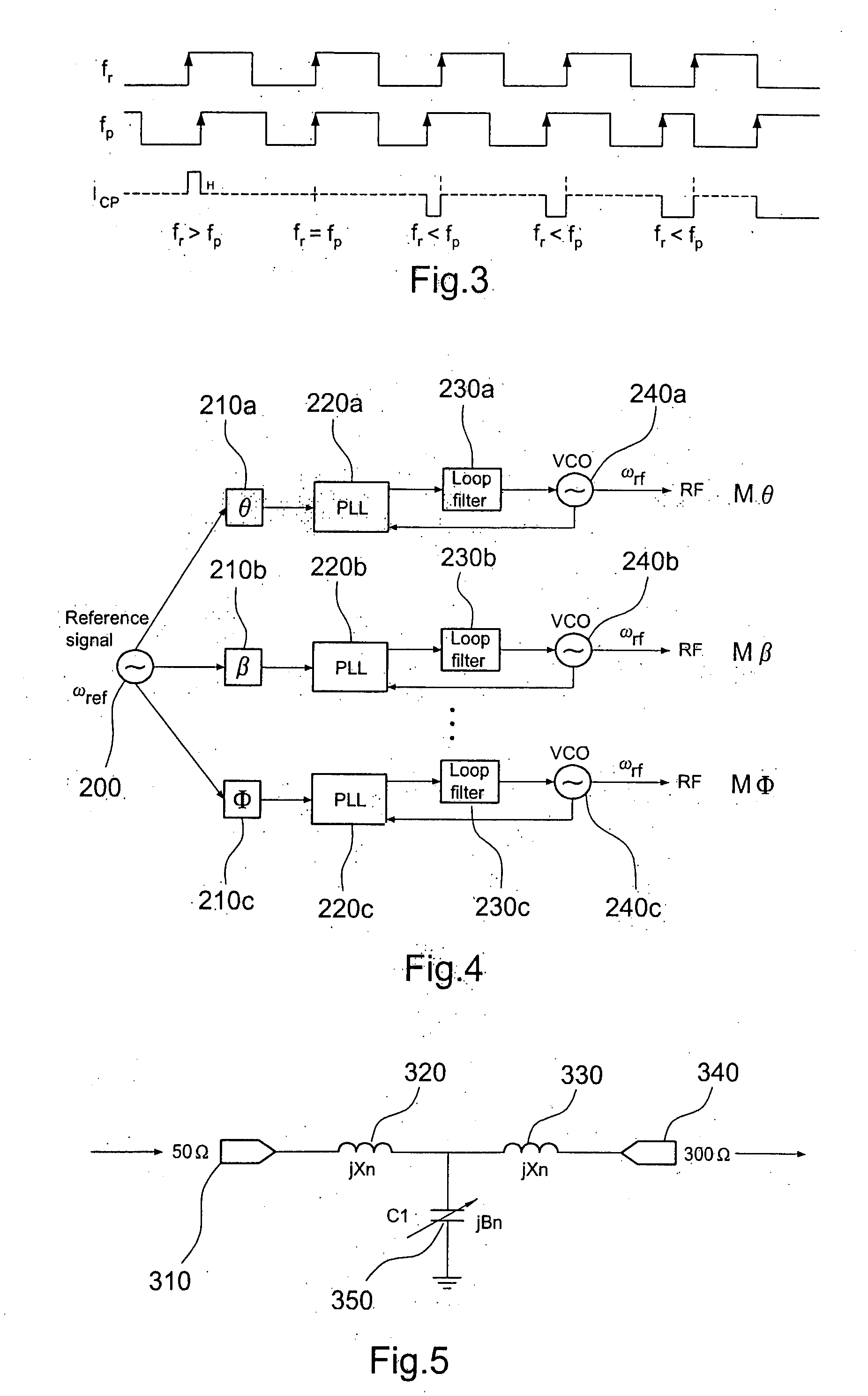
[0008]A first aspect of the present invention provides a source of radiation comprising[0009]a first oscillator for providing a reference signal having a phase;[0010]a plurality of phase shifters coupled to said first oscillator, each phase shifter being arranged for phase shifting said reference signal and transmitting a respective phase shifted reference signal;[0011]a plurality of phase locked loops, each phase locked loop having a respective Voltage Controlled Oscillator (VCO) for outputting a signal;[0012]wherein each said phase locked loop is coupled to a respective one of said phase shifters, and whereby in use each said VCO is phase locked to a reference signal which has been phase shifted by a respective one of said phase shifters.

[0013]Preferably the frequency of the reference signal provided by the first oscillator is less than the frequency of the signal output by the VCOs.

[0014]The reference signal may have any suitable frequency. The frequency of the reference signal m...


PUM


Abstract

A source of radiation comprises a first low frequency oscillator 200 for providing a reference signal and a plurality of phase shifters 210a, 210b, 210c coupled to the first oscillator. In addition there are a plurality of phase locked loops 230a, 230b, 230c, each phase locked loop having a respective Voltage Controlled Oscillator (VCO) 240a, 240b, 240c for outputting a signal. Each phased locked loop is coupled to a respective one of the phase shifters, so that in use each VCO is phase locked to a reference signal which has been phase shifted by a respective one of the phase shifters. In this way the phase of the radiation output by each VCO may be controlled indirectly by controlling the phase shift of the reference signal. In a preferred embodiment the phase shifters are adjustable to shift the phase by an adjustable amount.

Description

FIELD OF THE INVENTION[0001]The present invention relates to a source of radiation, preferably but not necessarily radio frequency radiation. The source may be a phased source in which the phase of the output radiation can be adjusted. One possible application of the invention is as a source for feeding a phased antenna array. It may be particularly advantageous when used for beam steering.BACKGROUND OF THE INVENTION[0002]Phased antenna arrays typically comprise a group of antennas in which the relative phases of the respective signals feeding the antennas are varied. The phases of the antennas may be arranged in such a way that the effective radiation pattern of the array is reinforced in a desired direction and suppressed in undesired directions. If the phases supplied to the respective antennas can be varied, then the direction of a beam transmitted by the array may be steered.[0003]The beam forming characteristics of phased array antennas make them attractive in the fields of ra...

Claims


Application Information

Patent Timeline
IPC IPC(8): H03L7/081
CPCH03L7/07H03L7/23
Inventor WAN, KWUN CHIUXUE, QUAN
Owner CITY UNIVERSITY OF HONG KONG
Why Eureka
Try Eureka