Liquid Crystal Optical Element

a technology of optical elements and liquid crystals, applied in the field of liquid crystal optical elements, can solve problems such as how to correct spherical aberration

Inactive Publication Date: 2008-10-30
CITIZEN WATCH CO LTD
View PDF3 Cites 12 Cited by
  • Summary
  • Abstract
  • Description
  • Claims
  • Application Information

AI Technical Summary

Benefits of technology

[0080]The liquid crystal optical element according to the present invention has an effect of solving the difference in the effective aperture of the objective lens in the case of using various types of laser lights such as the blue laser light, the red laser light, and the infrared laser light. T...

Problems solved by technology

However, since the spherical aberration is inversely proportional to the wavelength of the laser light, how...

Method used


Image

  • Liquid Crystal Optical Element
  • Liquid Crystal Optical Element
  • Liquid Crystal Optical Element

Examples


first embodiment

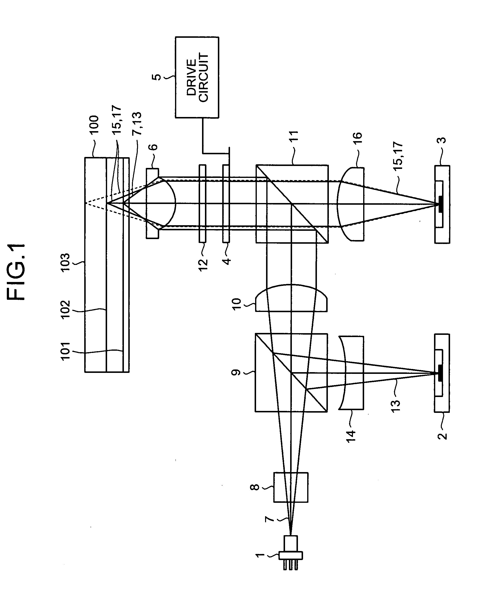
[0113]FIG. 1 is a diagram of a schematic configuration of an optical head device to which a liquid crystal optical element according to the present invention is applied. As shown in FIG. 1, the optical head device comprises a blue laser light source 1 that projects the blue laser light of a wavelength on the order of 400 nm, a blue-color-use photodiode 2 that detects a return light of the laser light projected from the blue laser light source 1, a DVD / CD-use module 3 that integrates a laser light source that projects a infrared laser light of a wavelength on the order of 780 nm and a red laser light of a wavelength on the order of 660 nm and a photodiode that detects respective return lights of these two laser lights, a liquid crystal cell 4 that makes up a major part of the liquid crystal optical element that performs a wave front control such as a spherical aberration correction, a drive circuit 5 that constitutes a power source unit of the liquid crystal optical element, and an o...

second embodiment

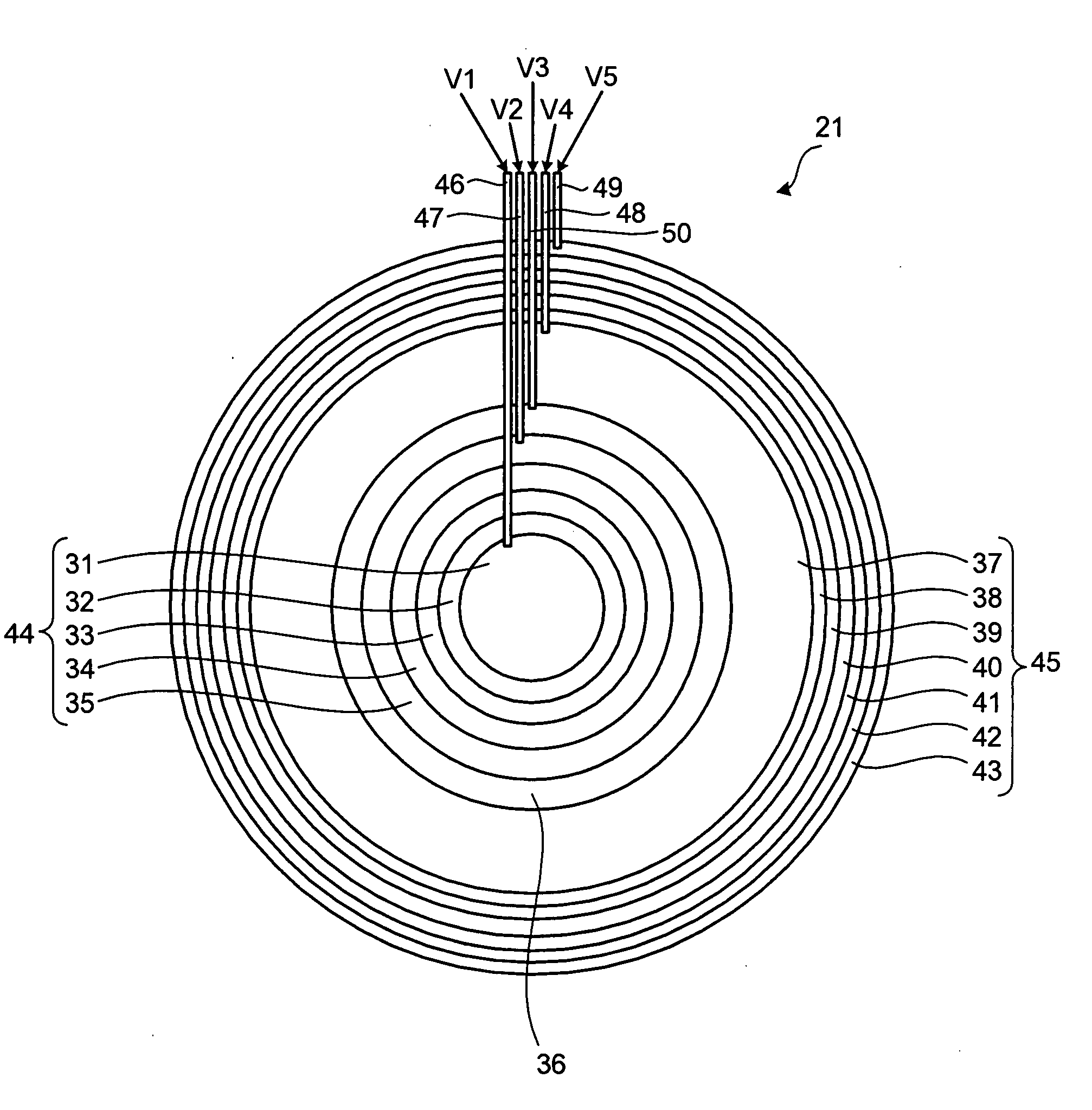
[0136]In a second embodiment, the concentric electrodes are provided for both of the first and second electrodes. The same configuration as that of the first embodiment will be affixed with the same numeral as that used in the first embodiment, with the description thereof being omitted. FIGS. 13 and 14 are diagrams of pattern of a first electrode 121 and a second electrode 123, respectively, in the second embodiment. FIG. 15 is a typical diagram of relationship between the first and second electrodes 121 and 123 and the voltages applied between them.

[0137]As shown in FIG. 13, the first electrode 121 has the 6th concentric electrode (independent concentric electrode) 36 and the 7th to 13th concentric electrodes 37 to 43 connected through resistors in the same way as in the first embodiment. The inner side of the 6th concentric electrode 36, namely, the area in which the 1st to 5th concentric electrodes 31 to 35 are provided in the first embodiment, has become a 14th concentric elect...


PUM


Abstract

A first electrode of a liquid crystal cell (21) is composed of a plurality of concentric electrodes (31 to 34) of a concentrically circular shape, the plurality of concentric electrodes are divided into a first group of concentric electrodes (44) near the center and a second group of concentric electrodes (45) near the periphery, and a concentric electrode between the two groups is an independent single electrode (36). A first correction unit that corrects spherical aberration of a high density DVD is composed of the two groups and a second correction unit that corrects aberration of a conventional DVD is composed of the first group of concentric electrodes (44). In the case of correcting the aberration of the conventional DVD, the independent concentric electrode (36) is supplied with a voltage between the voltages respectively supplied to adjacent concentric electrodes (35), (37). In the case of correcting the aberration of the high density DVD, the independent concentric electrode (36) is supplied with a voltage equal to the voltage supplied to the concentric electrode immediately lateral thereto (37).

Description

TECHNICAL FIELD[0001]The present invention relates to a liquid crystal optical element, and more particularly, to a liquid crystal optical element that makes correction of a fluctuation, a distortion, an aberration, etc., produced in a light wave-front when a light flux passes through a lens and is condensed.BACKGROUND ART[0002]Conventionally, optical disks such as a CD (compact disk) and DVD (digital versatile disk) are used as a medium for recording music data, video data, etc. An optical disk device condenses a laser light by a lens and irradiates it onto a data recording layer of an optical disk and, by detecting the light reflected thereby, reads out recorded data of the optical disk. An infrared laser light of a wavelength on the order of 780 nm and an objective lens with a numerical aperture on the order of 0.45 to 0.51 are used in reading out the recorded data of the CD.[0003]On the other hand, with respect to the DVD, since the data is recorded at the density higher than th...

Claims


Application Information

Patent Timeline
IPC IPC(8): G02F1/133G02F1/1343G11B7/135
CPCG02F1/134309G02F2203/18G11B7/1367G11B7/1369G11B7/13925G11B2007/0006
Inventor OSAWA, SEIICHISATO, SHINYAIWASAKI, MASAYUKITOYODA, TAKESHI
Owner CITIZEN WATCH CO LTD
Why Eureka
Try Eureka