

Solid electrolytic capacitor and method of manufacturing the same
a technology of electrolytic capacitors and solid electrolytic capacitors, which is applied in the manufacture of electrolytic capacitors, liquid electrolytic capacitors, electrolytic capacitors, etc., can solve the problems of reduced capacitance, and insufficient use of conducting polymer layers inside the anode body as capacitors, etc., to achieve the effect of increasing capacitan
- Summary
- Abstract
- Description
- Claims
- Application Information
AI Technical Summary
Benefits of technology
Problems solved by technology
Method used
Image

Examples
first embodiment
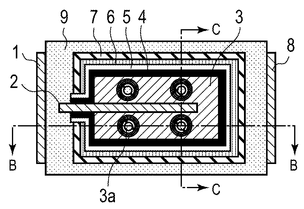
[0026]FIG. 1A is a cross-sectional view of a solid electrolytic capacitor according to a first embodiment. FIG. 1B is a cross-sectional view of the solid electrolytic capacitor taken along the line B-B of FIG. 1A. FIG. 1C is a cross-sectional view of the solid electrolytic capacitor taken along the line C-C of FIG. 1A. Descriptions will be provided hereinbelow for the structure of the solid electrolytic capacitor according to the first embodiment.
[0027]In the solid electrolytic capacitor according to this embodiment, as shown in FIG. 1, anode lead 2 is embedded in anode body 3. Anode lead 2 is made of a valve metal. Anode body 3 is formed in a cuboid shape by molding particles of a valve metal into the cuboid shape, and subsequently by sintering the resultant mold in vacuum.
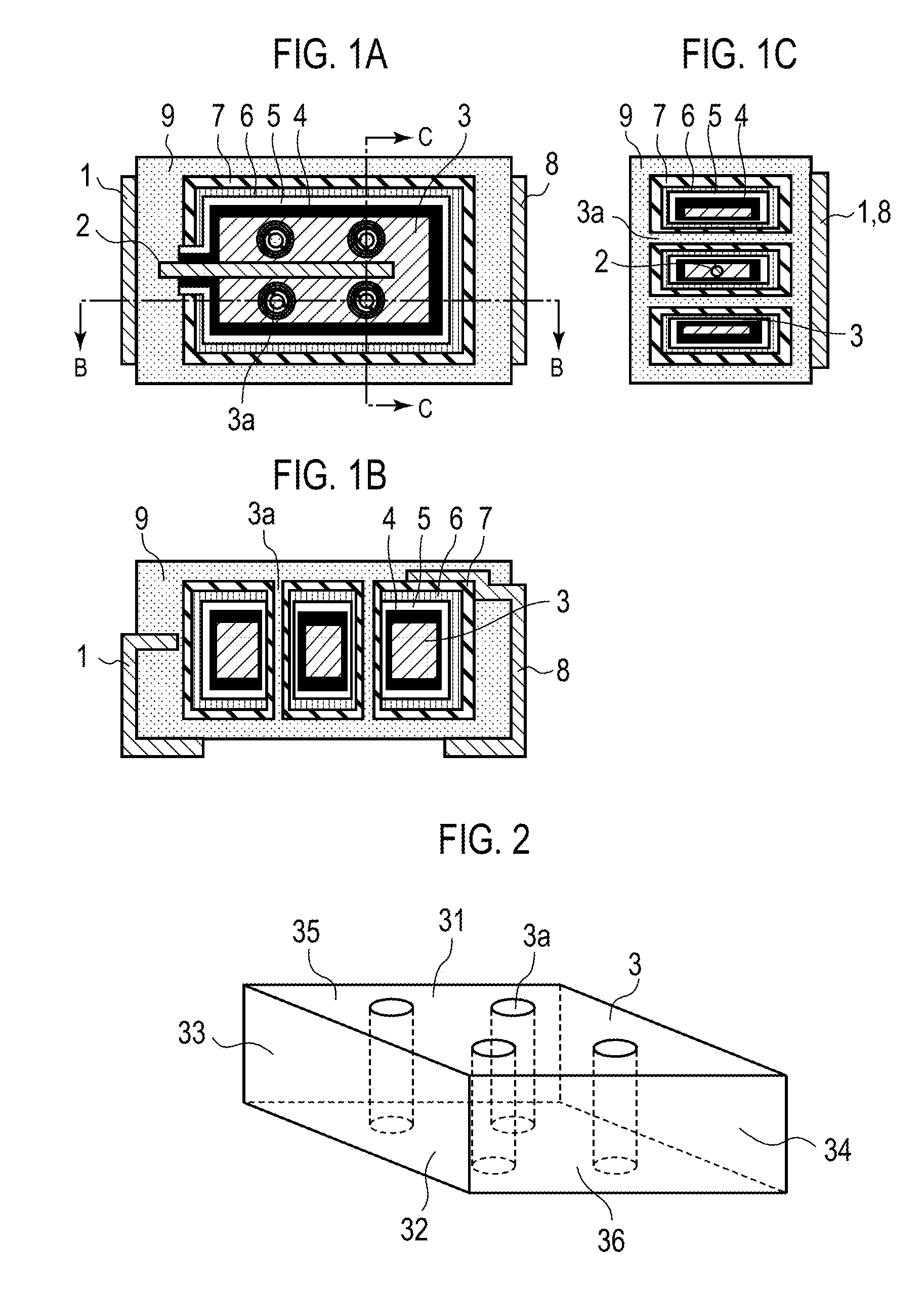
[0028]FIG. 2 is a perspective view of the anode body in the solid electrolytic capacitor according to the present embodiment. As shown in FIG. 2, anode body 3 includes multiple hole portions 3a, which penetrate a...
second embodiment
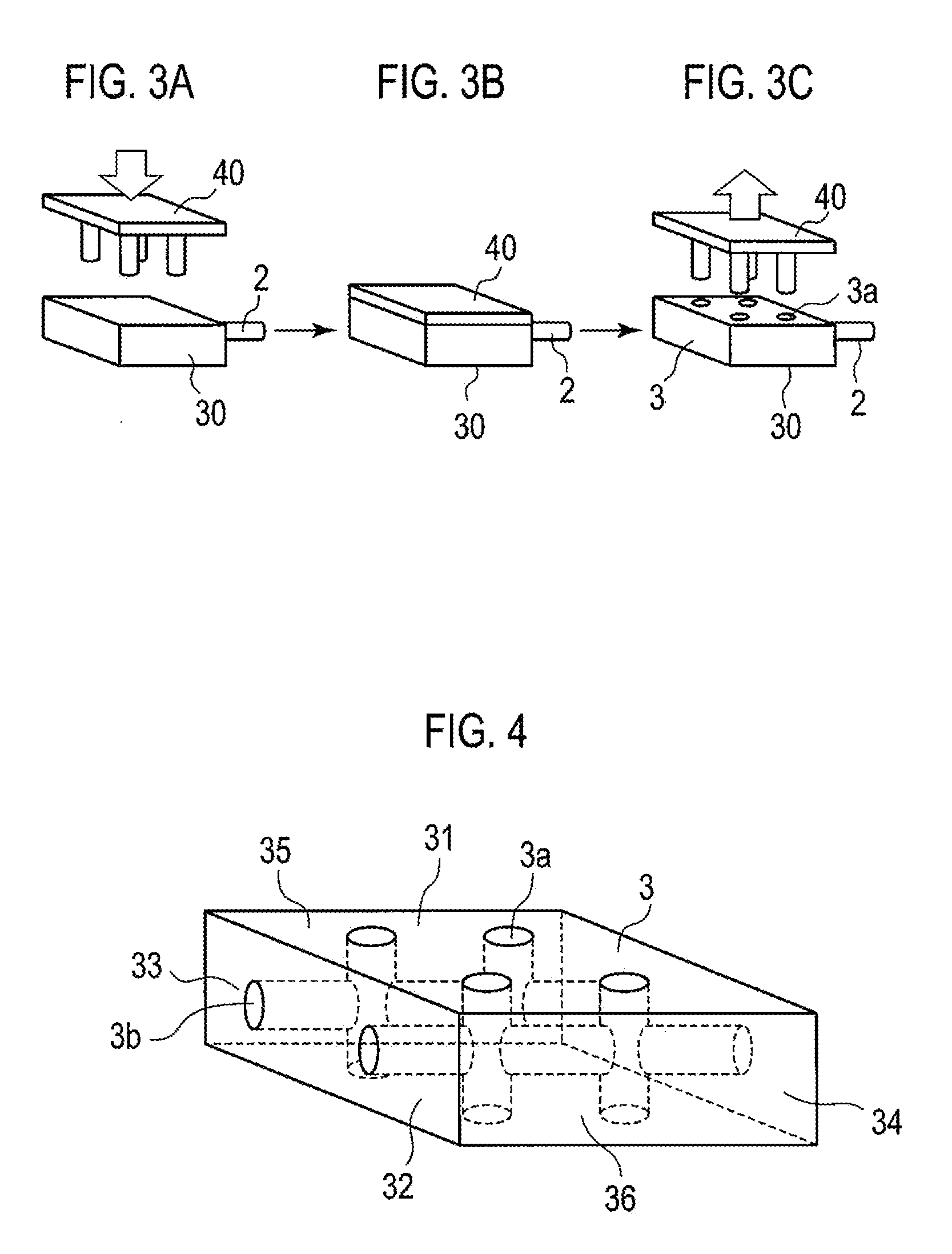
[0048]FIG. 4 is a perspective view of an anode body in a solid electrolytic capacitor according to a second embodiment. As shown in FIG. 4, anode body 3 includes multiple hole portions 3a that penetrate anode body 3 from first surface 31 to second surface 32, which is opposed to first surface 31, and hole portions 3b that penetrate anode body 3 from third surface 33 to fourth surface 34, which is opposed to third surfaces 33. Hole portions 3a are connected to hole portions 3b inside anode body 3. By use of anode body 3 thus formed, the solid electrolytic capacitor according to the second embodiment can form by including the same configuration as constructed in the first embodiment.
[0049]In this respect, the openings of hole portions 3a and 3b may each form in any surface as in the first embodiment.
[0050]The solid electrolytic capacitor according to the present embodiment can secure more paths for supplying monomer for conducting polymer layer 5 to the inside of anode body 3, because...
example 1
[0051]As the material for anode body 3, niobium powder having a CV value of 100,000 [μF·V / g] is used, where the CV value represents the product of capacitance and electrolytic voltage of a niobium sintered body on which an electrolytic oxidation film have been formed. The niobium powder and the binder are mixed and kneaded together, and mixed-kneaded niobium powder is thus prepared. Along with a metal wire made of tantalum with a diameter of 0.5 mm that later serves as anode lead 2, the niobium powder mixed and kneaded with the binder is formed into a shape with a size of 4.5 mm×3.3 mm×1.0 mm by use of the mold. (Four) holes (with 0.5 mmf) which penetrated the niobium-powder molded body are opened in the niobium-powder molded body by use of the piercing jig, as shown in FIG. 3. Subsequently, the binder is removed from the resultant niobium-powder molded body under a reduced pressure. The resultant niobium-powder molded body is sintered at 1100° C. As a result, anode body3 made of ni...
PUM
| Property | Measurement | Unit |
|---|---|---|
| Diameter | aaaaa | aaaaa |
| Diameter | aaaaa | aaaaa |
| Diameter | aaaaa | aaaaa |
Abstract
Description
Claims
Application Information