Method and Apparatus Adapted to Demodulate a Data Signal

Active Publication Date: 2008-10-30
SATO HLDG CORP
View PDF24 Cites 10 Cited by
  • Summary
  • Abstract
  • Description
  • Claims
  • Application Information

AI Technical Summary

Benefits of technology

[0014]Whilst, the inventors have realised that as an alternative to PPM, phase modulation has significant advantages in that bandwidth is narrower compared to PPM and thus significant data rate increases are possible. The detection of a phase modulated signal would typically be performed by a PLL. The inventors have realised that the purpose of a PLL in a prior art circuit is in effect to provide a stable phase reference. But in practice, although the phase of the PLL does not move quickly, but it does move slowly (drift), in a data dependant manner, resulting in Intersymbol Interference (ISI). The phase of a PLL may also be ‘moved’ a little in response to a, noise spike, for example. These spikes also cause noise at the circuit output as the PLL re-adjusts itself. In the present invention, a relatively fixed reference is provided in a form which is considered to be relatively more stable, offer lower noise and is relatively more adaptable for ASIC integration.
[0015]The present invention relates to an improvement on the method and apparatus disclosed in co-pending applications based on PCT/AU98/01077, the disclosure of which is herein incorporated by reference. PCT/AU98/01077 discloses the use of a Phased Locked Loop (PLL) as a part of the demodulation circuitry. It has been realised by the inventors that the PLL tends to ‘drift’ i

Problems solved by technology

These spikes also cause noise at the circuit output as the PLL re-adjusts itself.
The inventors have further found that a PLL may tend to suffer from noise associated probl

Method used


Image

  • Method and Apparatus Adapted to Demodulate a Data Signal
  • Method and Apparatus Adapted to Demodulate a Data Signal
  • Method and Apparatus Adapted to Demodulate a Data Signal

Examples


Example

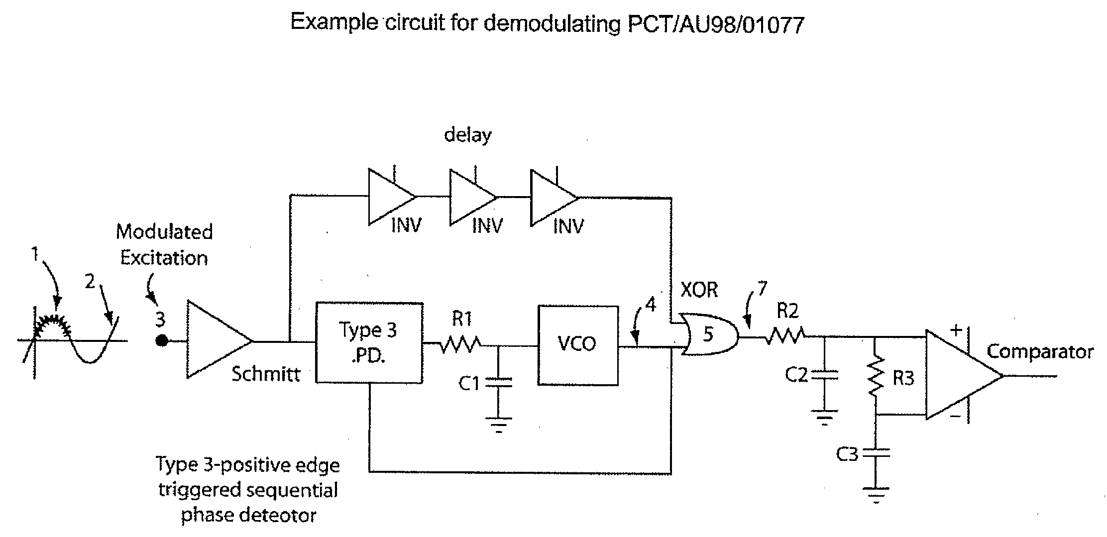
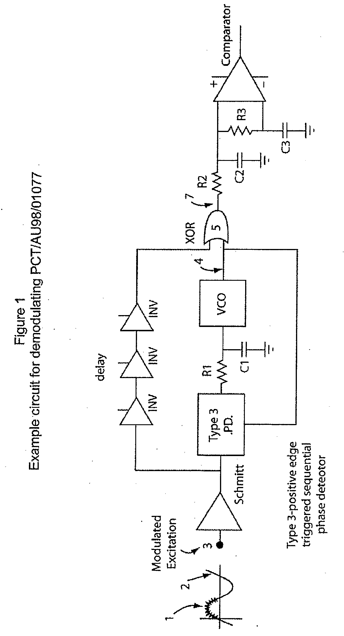
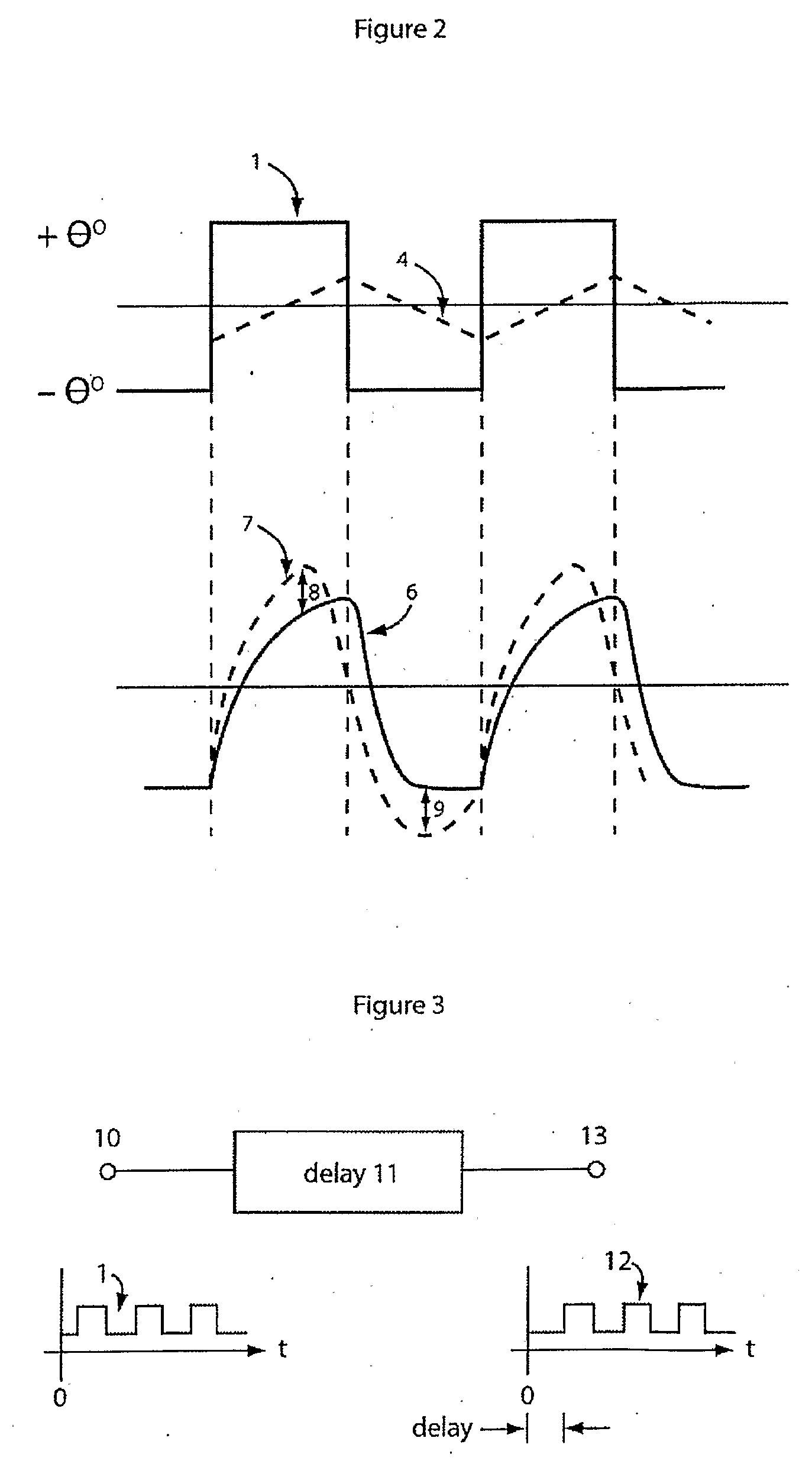
[0039]Referring to FIGS. 1 and 2 together, the signal 1 represented in FIG. 2 is a phase signal formed on a carrier signal 2 which is modulated excitation 3 input in FIG. 1. FIG. 2 illustrates more clearly the phase signal I which is imposed on the carrier signal 2 of FIG. 1. Also illustrated in FIG. 1 is a Phase Locked Loop (PLL) tracking signal 4. That is the effect of the phase signal on the circuit configuration of FIG. 1, in operation, is that the PLL ‘drifts’.

[0040]Also illustrated in FIG. 2 is a representation 6 of an ‘ideal’ recovered signal from the output of the XOR gate 5 of FIG. 1. However, in practice; the recovered signal from the output of the XOR gate 5 in FIG. 1 is more like signal 7 illustrated in FIG. 2. In FIG. 2, the difference between the ‘ideal’ signal 6 and the actual recovered signal 7 is shown, in part, by numerals 8 and 9. This difference is referred to as ISI. The inventors have found that the PLL has an inherent operational transient response which cause...


PUM


Abstract

The present invention relates to the field of receiving data and/or demodulating a data transmission signal. The present invention provides a method of and/or device for determining a data signal imposed on a phase jitter modulation signal. In one form, the invention relates to the field of Radio Frequency Identification (RFID), and the transmission of data between a tag and an interrogator.

Description

FIELD OF INVENTION[0001]The present invention relates to the field of receiving data and / or demodulating a data transmission signal.[0002]In one form, the invention relates to the field of Radio Frequency Identification (RFID), and the transmission of data between a tag and an interrogator.[0003]In another form, the present invention is suitable for recovering data received by a tag. The data signal is imposed on a carrier signal, for example a powering signal, received via an antenna.[0004]It will be convenient to hereinafter describe the invention in relation to a signal received by a tag from an interrogator, however it should be appreciated that the present invention is not limited to that use only.BACKGROUND ART[0005]The discussion throughout this specification comes about due to the realisation of the inventors and / or the identification of certain prior art problems by the inventors.[0006]The inventors have realised that in the past, data has been transmitted to RFID tags by m...

Claims


Application Information

Patent Timeline
IPC IPC(8): H04B5/00
CPCG06K19/0723H03D1/24H03L7/0812H04L25/4902H03D3/02H04L27/2331H03L7/0816
Inventor LITTLECHILD, STUART COLINMURDOCH, GRAHAM ALEXANDER MUNRO
Owner SATO HLDG CORP
Why Eureka
Try Eureka