
Fan motor driving circuit

a technology of motor driving and fan motor, which is applied in the direction of starter details, single-phase motor control, dynamo-electric converter control, etc., can solve the problems of increasing soft start voltage and not being able to execute the desired soft start, and achieve the effect of effective starting up

Active Publication Date: 2008-11-06
ROHM CO LTD
View PDF1 Cites 26 Cited by
  • Summary
  • Abstract
  • Description
  • Claims
  • Application Information

AI Technical Summary

Benefits of technology

[0011]The present invention has been made in view of such a problem, and a general purpose of the present invention is to provide a technique capable of effectively starting up in the case where a fan motor driving circuit is stopped in an unexpected procedure.
[0017]When the power supply is interrupted, the power supply voltage is gradually decreased. In this case, while the power supply voltage is continued to hold a movable level of a circuit element, the initialization switch is turned on. By performing this process, even when the power supply voltage is transited from on to off in addition to the case when the power supply voltage is transited from off to on, the capacitor can be initialized; and therefore, sureness of the process is increased.
[0020]According to this embodiment, the current flowing through the coil of the fan motor is suppressed to not higher than a current value specified by the voltage output from the variable reference voltage circuit. The current flowing through the coil of the fan motor is also slowly increased by slowly increasing the voltage output from the variable reference voltage circuit in starting up; and therefore, it can be suitably started up.
[0026]The fan motor driving circuit may be monolithically integrated on one semiconductor substrate. The “monolithically integrated” includes a case where all of constituent elements of the circuit are formed on the semiconductor substrate, or a case where major constituent elements of the circuit are monolithically integrated, and some resistors and capacitors may be provided on the outside of the semiconductor substrate for adjusting circuit constant. The fan motor driving circuit is integrated as one LSI; and accordingly, a circuit area can be reduced.

Problems solved by technology

However, when the power supply voltage to the fan motor driving circuit is instantaneously interrupted by an unexpected method different from the normal procedure, the circuit is shut down without discharging the charge stored in the capacitor.
In this case, when the fan motor driving circuit is started up in the next, the soft start voltage is started to increase from the value; and therefore, it is not possible to execute the desired soft start.

Method used


Image

  • Fan motor driving circuit
  • Fan motor driving circuit
  • Fan motor driving circuit

Examples


first preferred embodiment

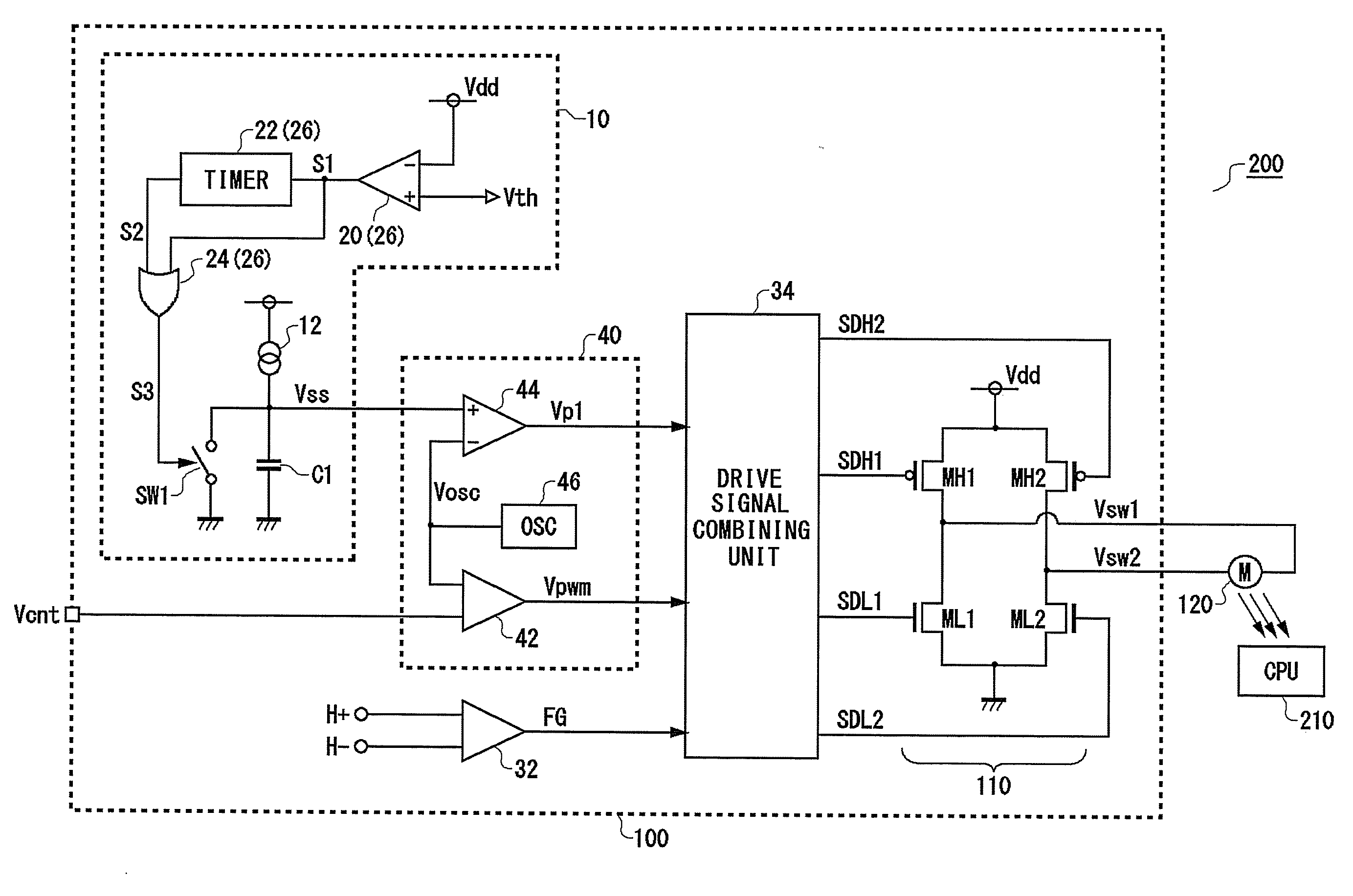
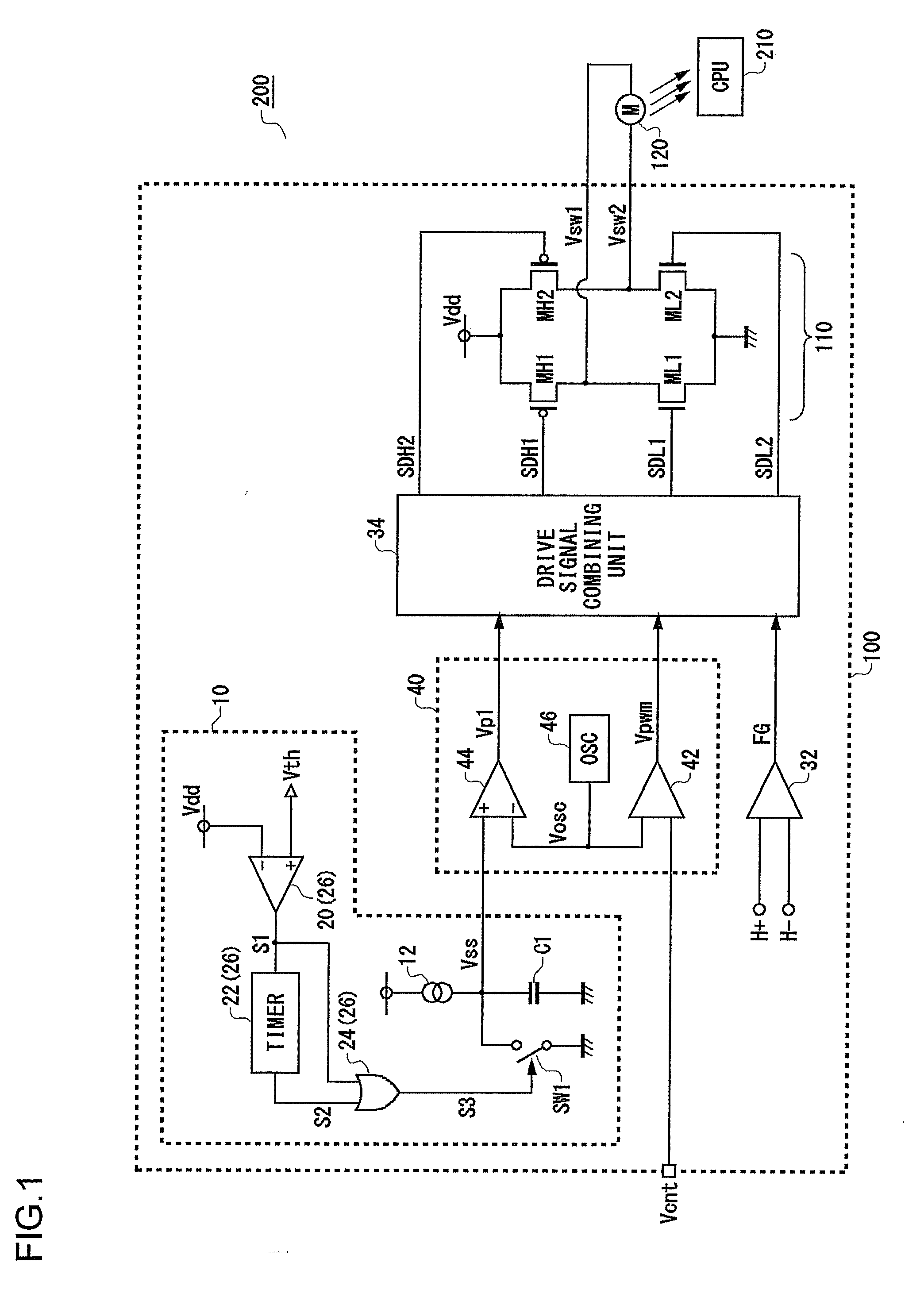
[0038]FIG. 1 is a circuit diagram showing a configuration of a cooling device 200 according to a first preferred embodiment. FIG. 1 shows a configuration of a part of an electronic computer, and the cooling device 200 and a central processing Unit (CPU) 210 of a cooling object are included. The cooling device 200 includes a fan motor driving circuit 100 and a fan motor 120.

[0039]The fan motor 120 is a single phase full wave motor and is arranged in opposition to the CPU 210 in the preferred embodiment. In the fan motor 120, a coil current, that is, an energized state is controlled by switching voltages Vsw1 and Vsw2 which are generated by the fan motor driving circuit 100 and rotation is controlled.

[0040]A switching circuit 110 includes a first high side transistor MH1, a second high side transistor MH2, a first low side transistor ML1, and a second low side transistor ML2; and accordingly, an H bridge circuit is constituted.

[0041]On and off of the transistors MH1 and ML1 are contro...

second preferred embodiment

[0075]FIG. 3 is a circuit diagram showing a configuration of a fan motor driving circuit 100a according to a second preferred embodiment. Only different points from the fan motor driving circuit 100 shown in FIG. 1 will be described below.

[0076]The fan motor driving circuit 100 shown in FIG. 1 is started up by slowly increasing the duty ratio of the pulse signal which is for controlling the switching circuit 110. On the contrary, the fan motor driving circuit 100a shown in FIG. 3 detects a coil current IM flowing into a fan motor 120, and controls an energization time of the fan motor 120 so that the coil current IM does not exceed an upper limit current Imax. In starting up, the fan motor driving circuit 100a slowly increases the upper limit current Imax. As a result, the fan motor can be suitably started up.

[0077]The fan motor driving circuit 100a shown in FIG. 3 includes a hall comparator 32, a pulse width modulator 40a, a current limit circuit 30, a drive signal combining unit 3...


PUM


Abstract

A fan motor driving circuit controls an energized state of a fan motor by performing on and off control of a switching circuit connected to a coil of the fan motor of a driving object. A variable reference voltage circuit generates a voltage whose voltage level changes with time by charging or discharging a capacitor at the start of starting up the fan motor. A drive signal combining unit generates drive signals on the basis of the voltage when at least starting up, and performs on and off control of the switching circuit by the drive signals. An initialization circuit initializes the capacitor before starting up with a transition from off to on of a power supply voltage to be supplied to the fan motor driving circuit as a turning point.

Description

BACKGROUND OF THE INVENTION[0001]1. Field of the Invention[0002]The present invention relates to a motor driving technique and, more particularly, relates to a control when starting up a motor.[0003]2. Description of the Related Art[0004]In order to rotate a single-phase motor and a multi-phase motor at a desired torque, there is widely used a technique which controls an energization period of a motor coil by a pulse signal such as pulse width modulation signals.[0005]In the case where driving of a stopped motor is started, when a switching voltage having a pulse width corresponding to a target torque is suddenly applied to a motor coil, an electric current is suddenly flown to the motor coil. The current flowing through the coil becomes a value in which the applied voltage is divided by a winding resistance because there is no generating function when starting up the motor, specifically, in the case where the number of rotation thereof is near to 0. A resistance value of the coil i...

Claims


Application Information

Patent Timeline
Patent Type & Authority Applications(United States)
IPC IPC(8): H02P1/04H02P6/20H02P6/06H02P6/08H02P6/26
CPCH02P1/04H02P7/29
Inventor HAYASHI, HIROAKI
Owner ROHM CO LTD
Learn More