Connectorized nano-engineered optical fibers and methods of forming same

a nano-engineered, optical fiber technology, applied in the direction of cladding optical fibers, manufacturing tools, instruments, etc., can solve the problems of macrobending losses, time-consuming connectorization process, and high cost of highly trained technicians, and achieve the effect of preventing or eliminating contamination

Inactive Publication Date: 2008-11-06
CORNING OPTICAL COMM LLC
View PDF9 Cites 7 Cited by
  • Summary
  • Abstract
  • Description
  • Claims
  • Application Information

AI Technical Summary

Benefits of technology

[0013]In various embodiments, the present invention provides for the elimination of or the prevention of trapped contamination in airlines around the fiber core of a nano-engineered fiber by collapsing the airlines prior to connect

Problems solved by technology

In the early days of fiber optic systems, the use of connectors was problematic because poor connections introduced attenuation, and the connectorization process was time-consuming and required highly trained technicians.
Attendant with the increased use of fiber optic systems are issues relating to deploying optical fiber cables wherein the cables need to be bent to accommodate the geometry of a pre-existing structure or infrastructure.
Improper handling and deployment of a fiber optic cable can result in macrobending losses, also known as “extrinsic losses.” In ray-optics terms, severe bending of an optical fiber can cause the angles at which the light rays reflect within the fiber to exceed the critical angle of reflection.
For example, contaminants can fill the fiber voids at the fiber end face and ingress into the fiber, thereby reducing the efficiency of the connection.
One such contaminant is moisture.
Other contaminants include micro-debris generated at the connector end face during the connector polishing processes, such as mixtures of zirconium ferrule material and silica glass removed during polishing, abrasives from polishing films, and deionized water.
These contaminants may become trapped or embedded in the airlines at the connector end face.
Due to the various forces and attendant heat the connector end experiences during the polishing process, it is extremely difficult to remove the contaminants once they are in place.
In addition, contamination in the fiber that is freed during operation and/or handling of the fiber and that moves across the connector end face into the fiber core region may also increase signal attenuation.
W

Method used


Image

  • Connectorized nano-engineered optical fibers and methods of forming same
  • Connectorized nano-engineered optical fibers and methods of forming same
  • Connectorized nano-engineered optical fibers and methods of forming same

Examples


Embodiment Construction

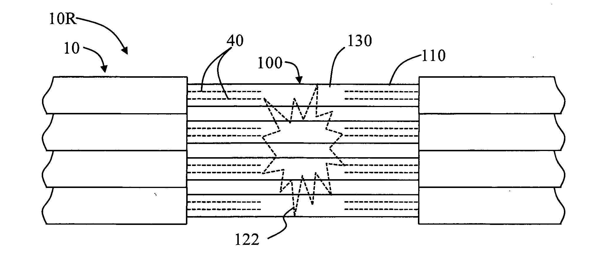
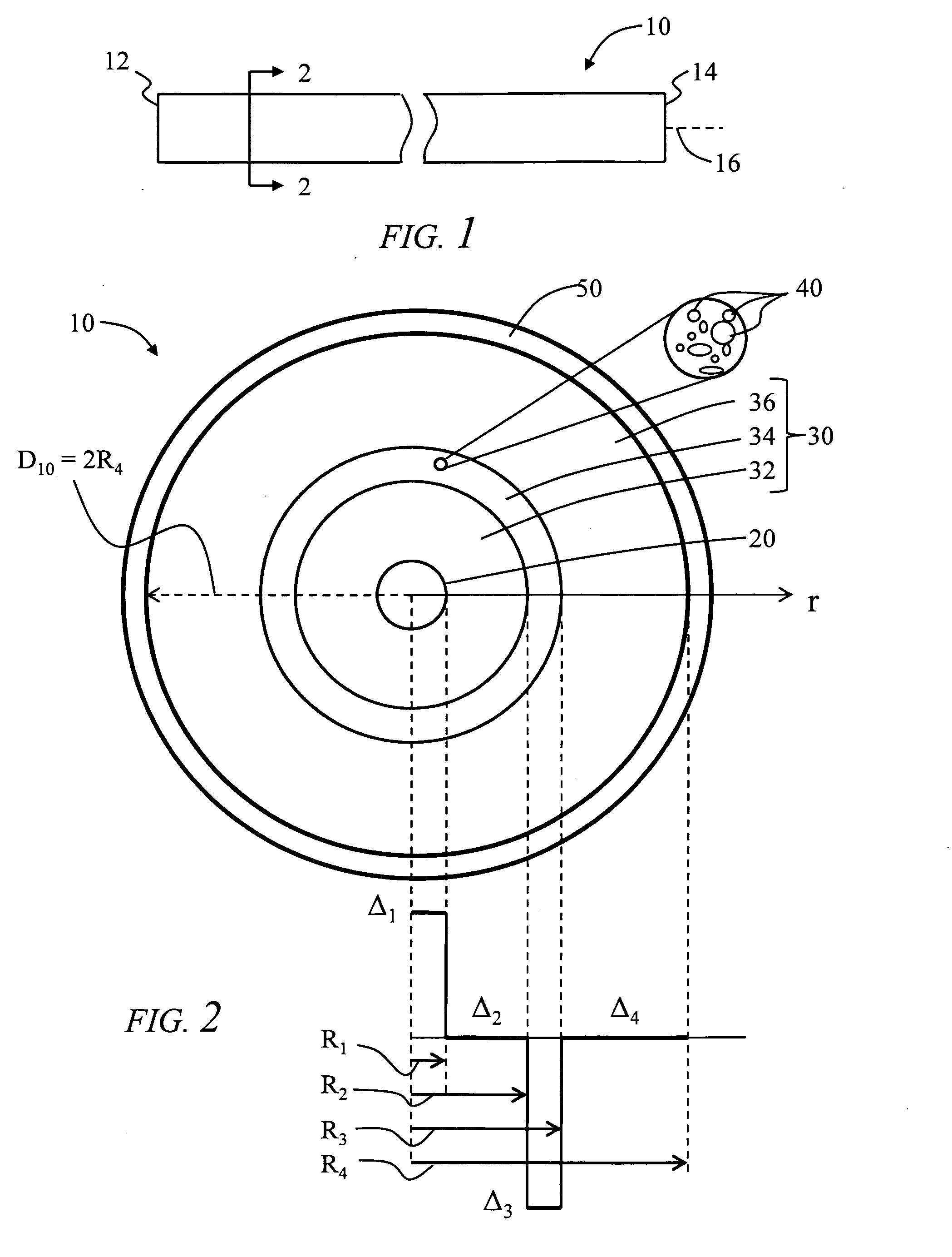
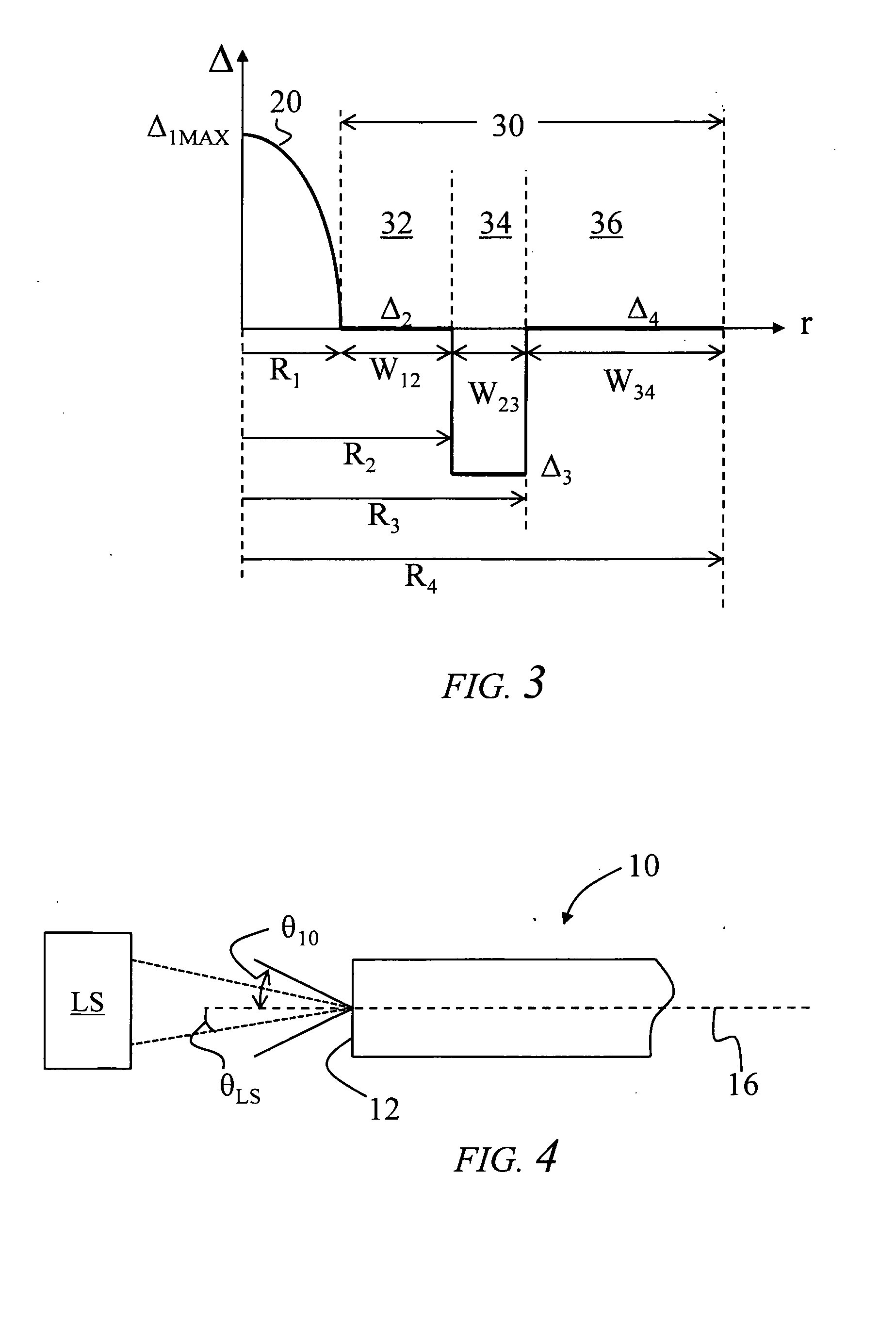
[0038]Reference is now made to preferred embodiments of the invention, examples of which are illustrated in the accompanying drawings. Whenever possible, the same reference numbers and symbols are used throughout the drawings to refer to the same or like parts.

Definitions and Terminology

[0039]In the description below, the “refractive index profile” is the relationship between refractive index or relative refractive index and waveguide fiber radius. The “relative refractive index percent” is defined as Δi(%)=[(ni2−rc2) / 2ni2]×100, where ni is the maximum refractive index in region i, unless otherwise specified, and nc is the average refractive index of the cladding region, as discussed below. In an example embodiment, nc is taken as the refractive index of an inner annular cladding region 32, as discussed below.

[0040]As used herein, the relative refractive index percent is represented by Δ(%) or just “Δ” for short, and its values are given in units of “%”, unless otherwise specified o...


PUM

PropertyMeasurementUnit
Lengthaaaaaaaaaa
Lengthaaaaaaaaaa
Fractionaaaaaaaaaa

Abstract

Connectorized nano-engineered optical fibers and method for forming them are disclosed. The methods include heating a mid-span bare fiber portion of the nano-engineered fiber to collapse the airlines therein so as to form an airline-free portion. The fiber is then inserted into a ferrule channel so that the fiber end protrudes beyond the ferrule end face, but with the airline-free portion positioned at the ferrule end face. The fiber is then cleaved at or near the ferrule end face in the airline-free portion, and the new fiber end face polished to create a solid fiber end face that coincides with the ferrule end face. The methods result in at most only minimal changes to the mode field diameter (MFD) and/or to the outer cladding diameter, which is essential in forming a connectorized nano-engineered fiber that can connect to like-size nano-engineered or non-nano-engineered fibers.

Description

CROSS-REFERENCE TO RELATED APPLICATIONS[0001]This application claims the benefit of priority under 35 U.S.C. §119(e) of U.S. Provisional Application Serial No. U.S. Parent Provisional Application Ser. No. 60 / 927,430 filed on U.S. Parent Provisional Application Filing Date of May 3, 2007, which application is incorporated by reference herein.[0002]This application is also related to U.S. patent application Ser. No. 11 / 595,365, entitled “Method of splicing an optical fiber with holes in the cladding,” filed in the United States on Nov. 9, 2007, which application is incorporated by reference herein.BACKGROUND OF THE INVENTION[0003]1. Field of the Invention[0004]The present invention relates generally to connectorized optical fibers, and more specifically, to methods for collapsing airlines in the cladding of nano-engineered optical fibers that seeks results in a connectorized fiber with at most only minimal changes to the mode-field diameter and / or the outer cladding diameter of the fi...

Claims


Application Information

Patent Timeline
IPC IPC(8): G02B6/26G02B6/245
CPCG02B6/02333G02B6/02357G02B6/02376G02B6/25G02B6/3863Y10S977/762
Inventor BESHEARS, ROBERT R.BOOKBINDER, DANA C.COOKE, TERRY L.JOHNSON, JOHN B.KNECHT, DENNIS M.LI, MING-JUN
Owner CORNING OPTICAL COMM LLC
Why Eureka
Try Eureka