System for the production of synthetic fuels

Inactive Publication Date: 2008-11-06
FOREST ENERGY SYST
View PDF43 Cites 49 Cited by
  • Summary
  • Abstract
  • Description
  • Claims
  • Application Information

AI Technical Summary

Benefits of technology

[0017]In a preferred embodiment of the invention, the chemical reactions take place in an organic liquid phase. The hydrocarbon output of reactions in accordance with the invention can be recycled and use as the organic liquid, such as that combined with the initial feedstock, to ensure a substantially air free system and to assist in the downsizing of the feedstock solids. The recycled hydrocarbon output is at elevated temperature. Thus, the recycled stream aids in the initial elevation of feedstock temperature and reduces instances of charring. Recycling the output can also lead to branched chain hydrocarbons, which tend to increase octane or cetane ratings.
[0019]Preferred reactors are in the form of horizontal tubes. The tubes are preferably formed of steel. The tubes are capable of containing liquid at over 700° F. and 500 psig. An internal screw is used to move the reactants in plug-flow, through the reactor at controlled speeds. Electrical heating elements on the reactor surfaces advantageously control the temperature of the reactors. Measuring the temperature and viscosity at the output can provide valuable feedback for controlling the heating elements and screw speed.

Problems solved by technology

The feedstock can comprise scrap rubber, plastic and / or organic matter or other materials that are not particularly well suited for use as fuels in their existing state.

Method used


Image

  • System for the production of synthetic fuels
  • System for the production of synthetic fuels
  • System for the production of synthetic fuels

Examples


example i

[0060]

Feedstock75 g (30% wood, 30% hay, 15% switchgrass, 25% styrene / butadiene polymericplastic)Feedstock particle sizeMoisture content15%Initiator25 g of iron (Fe)Initiator particle sizeSolventMixture of organic liquids (alkanes ofcarbon number C5 to C21)Polymerization temperature700-800° F.Polymerization duration3-20 minutesProduct95% C3 to C21 molecules, 5% carbonnumber greater than 21

example ii

[0061]

Feedstock100 g of pure wood celluloseFeedstock particle size500 microns or lessMoisture content20%Imitator10 g of copper (Cu) and 10 g of zinc (Zn)Initiator particle sizeSolvent100 g of diesel fuelPolymerization temperature600° F.Polymerization duration10 minutesProduct93% C6 to C12 alkanes and alkanols, 7%C12 to C21 alkanes and alkanols

example iii

[0062]

Feedstock100 g of hayFeedstock particle sizeMoisture content7%Imitator5 g of platinum (Pt)Initiator particle sizeSolvent100 g of combined liquid products ofExample I and Example IIPolymerization temperature850° F.Polymerization duration15 minutesProduct94% C6 to C12 alkanes and alkanols, 6%C12 to C18 alkanes and alkanols

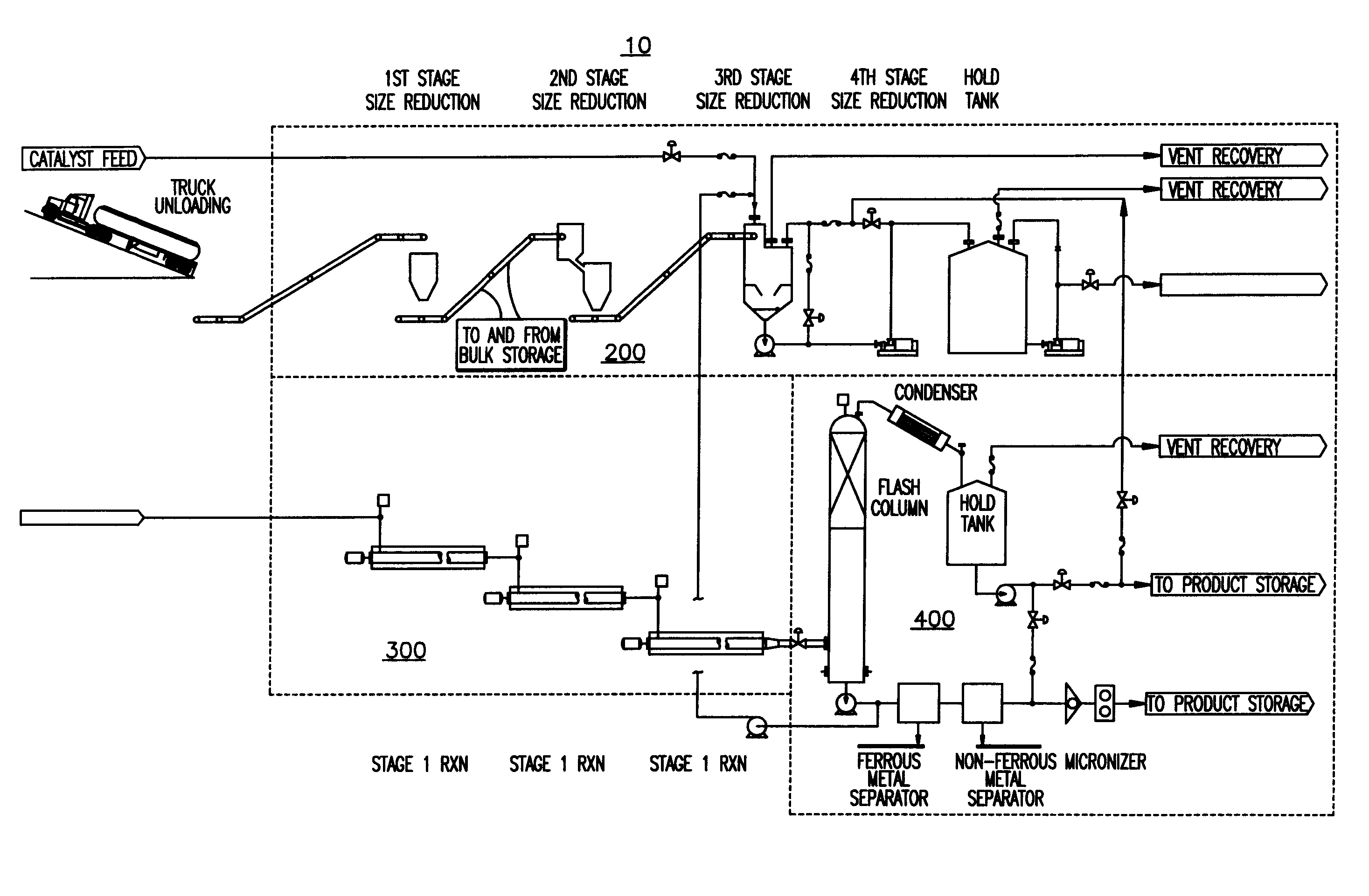
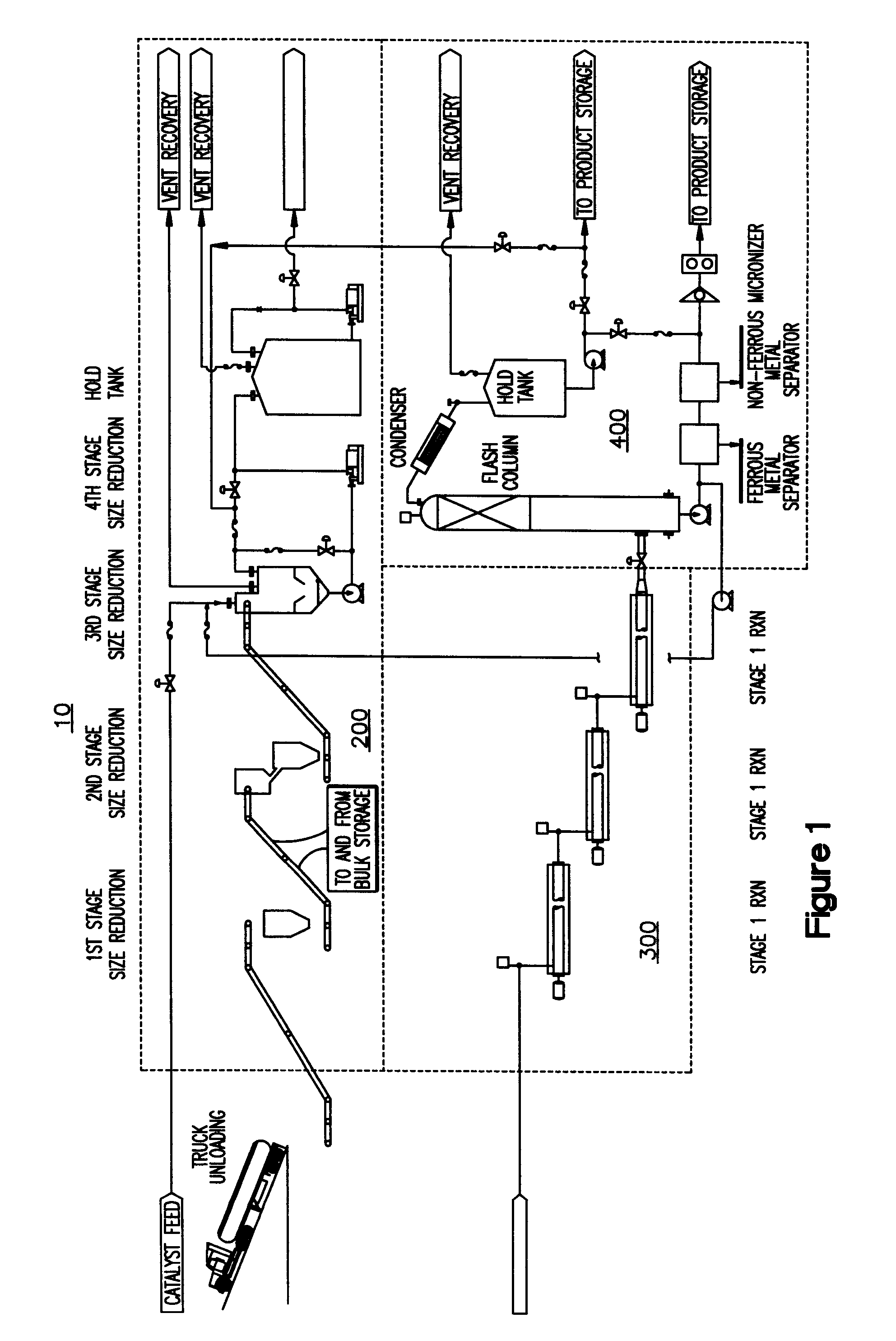
[0063]The above examples show the variety of feedstocks that can be used in the system to produce different synthetic fuels in accordance with the invention. The type of synthetic fuel produced can be controlled by the type of initiator used as well as reaction conditions such as those within third reactor 330. It is understood that in first and second reactors 310, 320, the feedstock is substantially liquefied by breaking intermolecular bonds using increased temperature and the reaction between the water and metal catalyst initiators. Feedstock is broken into short chain hydrocarbon radicals, ready to combine with others and polymerize. In third reactor 330, t...


PUM


Abstract

A system is provided for producing synthetic fuels. A feedstock containing polymers from a wide variety of sources is re-formed into a more satisfactory fuel source in one or more reactors. The reactor can be tube shaped and have an internal auger. The reactor can be non vertical, preferably horizontal. It can include electrical heating elements and can control both temperature and time of reaction. Feedstocks in accordance with the invention can include a wide variety of sources of cellulose or scrap plastic and tires. The process can be environmentally friendly, producing no net greenhouse gases.

Description

CROSS REFERENCE TO RELATED APPLICATIONS[0001]This application claims priority to provisional application No. 60 / 927,552, the contents of which are incorporated herein by reference.BACKGROUND OF THE INVENTION[0002]Wood and coal have been a principle source of fuel for hundreds of years. In modern times, petroleum has become a primary commodity for the generation of energy. Petroleum has had the advantages of relatively low cost and ease of transportation and storage because of its liquid consistency. Further, petroleum is readily amenable to fractionation and conversion into a variety of valuable industrial products such as fuels, building products, chemical intermediates and the like.[0003]International developments have led to increase in the price of this crude oil. The consumption of petroleum has been increasing exponentially and concomitantly the readily available world petroleum supply has diminished. Governments and industrial concerns are dedicating increased attention to al...

Claims


Application Information

Patent Timeline
IPC IPC(8): B01J19/02
CPCC10G1/08C10G1/10C10L1/02C10L1/04Y02P30/00
Inventor BOYKIN, JACK W.BOYKIN, ALLEN W.
Owner FOREST ENERGY SYST
Why Eureka
Try Eureka