Storage controller and storage controller control method

a storage controller and control method technology, applied in instruments, climate sustainability, data conversion, etc., can solve the problems of increasing the total cost of operation (tco) of the storage controller, increasing the power consumption of the hard disk drive, and increasing the power consumption of the storage controller. , to achieve the effect of relatively low power consumption and relatively high power consumption

Inactive Publication Date: 2008-11-06
HITACHI LTD
View PDF9 Cites 27 Cited by
  • Summary
  • Abstract
  • Description
  • Claims
  • Application Information

AI Technical Summary

Benefits of technology

[0015]In an embodiment of the present invention, the controller can control a prescribed data storage destination on the basis of the schedule such that the storage destination becomes the first storage device during a time period when the cost of power is relatively high, and becomes the second storage device during a time period when the cost of power is relatively low.

Problems solved by technology

Thus, a hard disk drive consumes a larger amount of power than a storage device such as a semiconductor memory.
Therefore, the power consumption of the storage controller increases.
As power consumption increases, the total cost of operation (TCO) of the storage controller also rises.
However, due to the physical structure of its cells, a flash memory device is limited as to the number of writes it can perform.
Further, since a charge stored in a cell diminishes over time, storing data over a long period requires the execution of refresh operations at regular intervals.
Since a storage controller is required to stably stored large amounts of data for a long period of time, it is difficult to use flash memory devices as-is.
Even if both flash memory devices and hard disk drives could be mounted in a storage controller, it is impossible to reduce the amount of power consumed by the storage controller as a whole when accesses from a host computer focus on the hard disk drives.

Method used


Image

  • Storage controller and storage controller control method
  • Storage controller and storage controller control method
  • Storage controller and storage controller control method

Examples


first embodiment

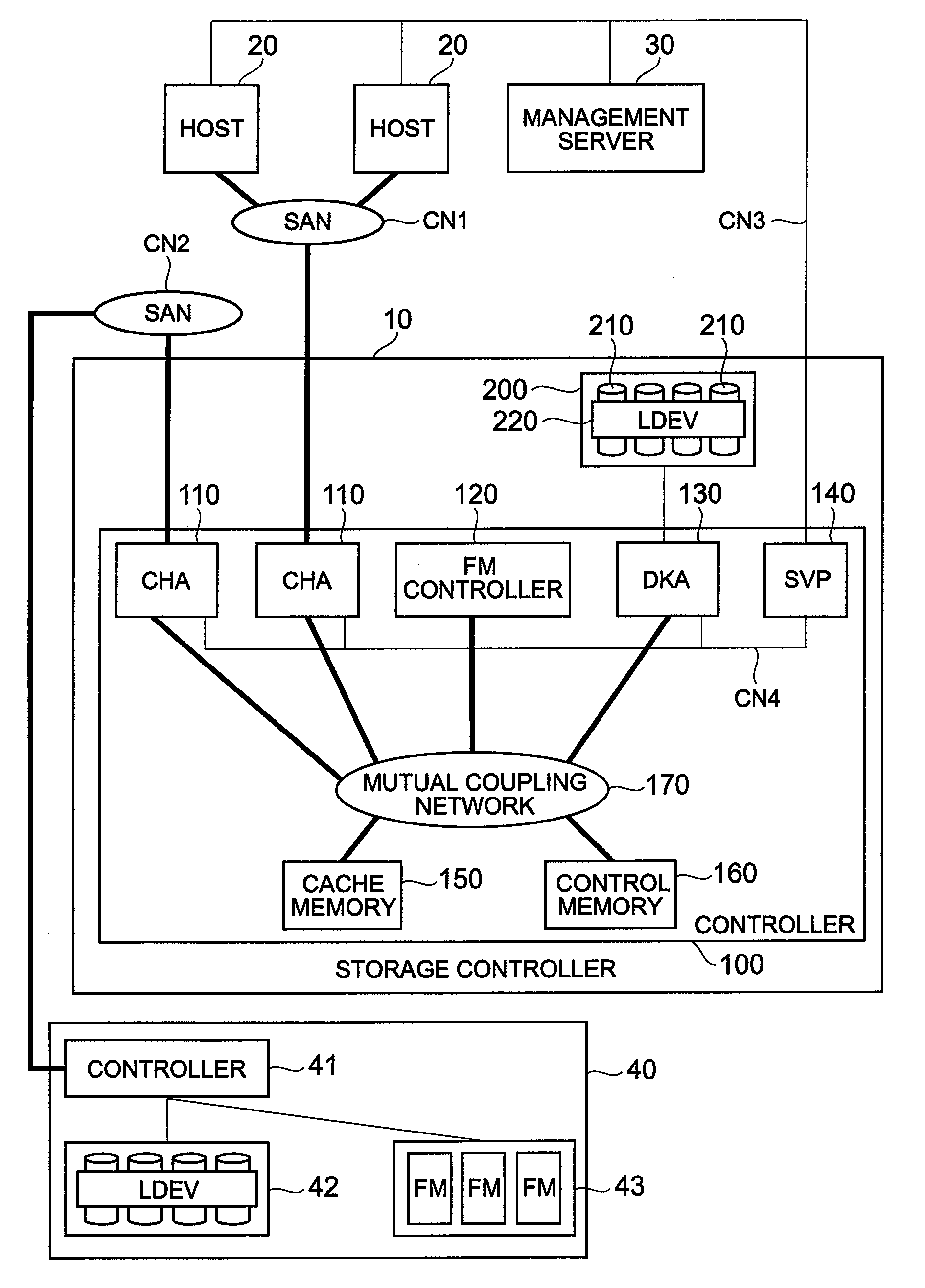
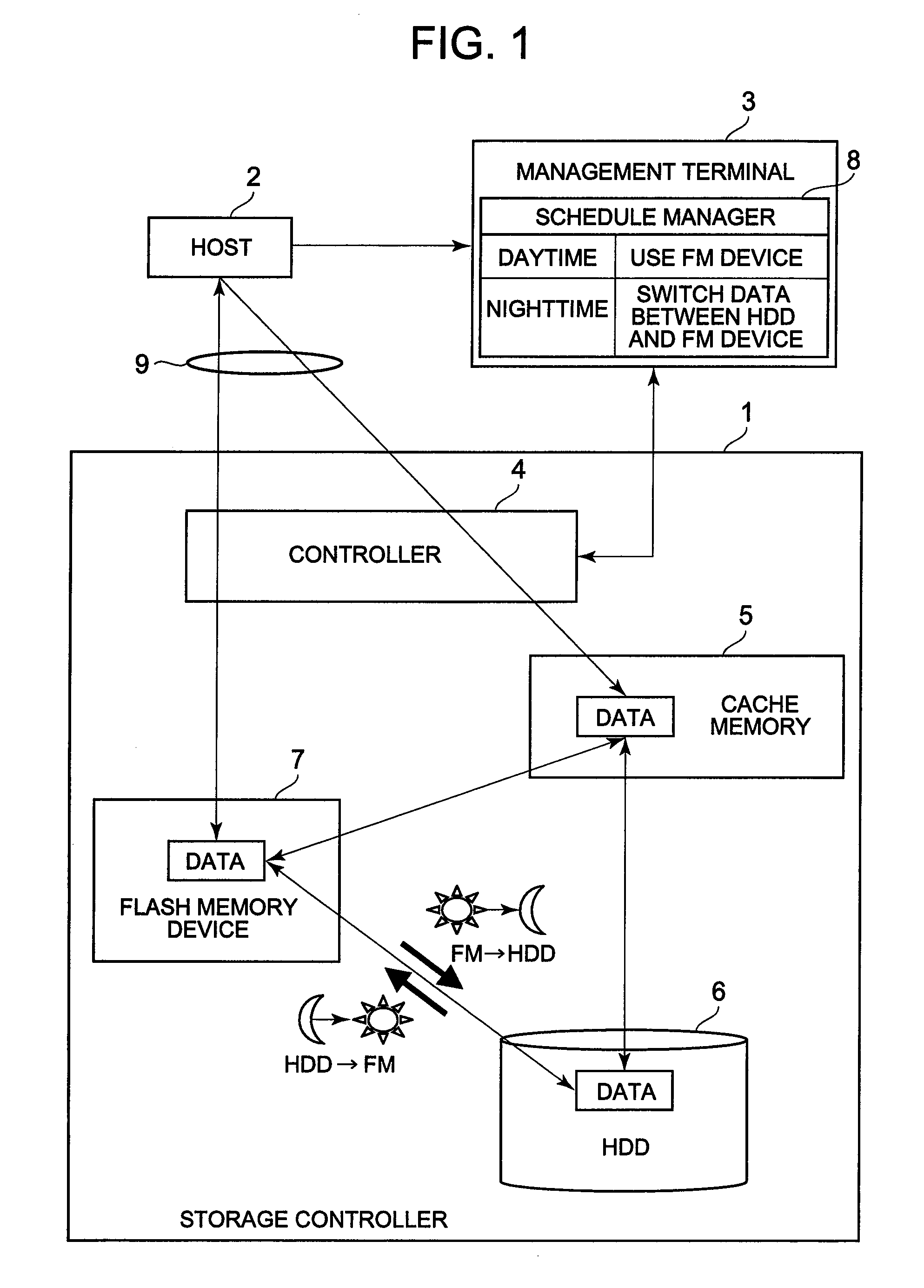
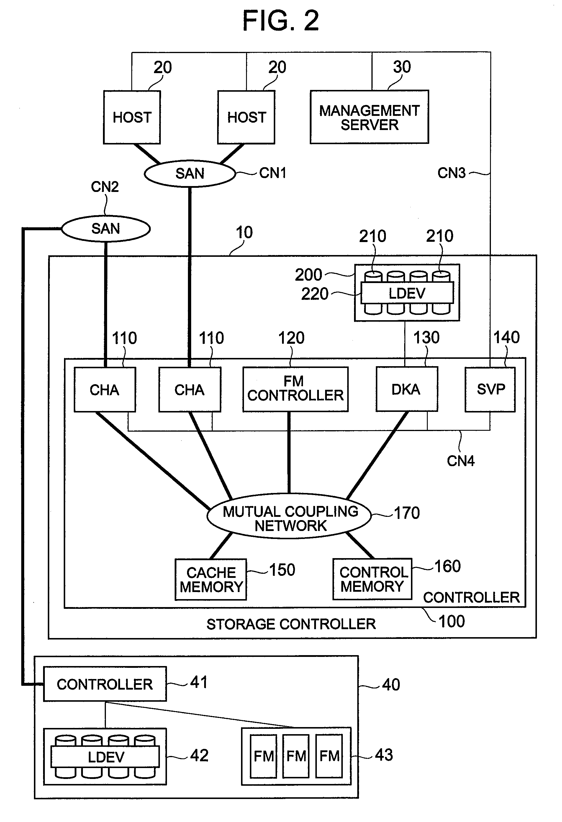
[0068]FIG. 2 is a schematic diagram showing the overall constitution of a storage system comprising a storage controller 10 according to this embodiment. This storage system, for example, comprises either one or a plurality of storage controllers 10, either one or a plurality of hosts 20, and at least one management server 30. The storage system can also comprise a separate storage controller 40. The storage controller 10 corresponds to the storage controller 1 of FIG. 1. The host 20 corresponds to the host 2 of FIG. 1. The management server 30 corresponds to the management terminal 3 of FIG. 1. Details concerning the storage controller 10, host 20, management server 30 and external storage controller 40, will be respectively explained hereinbelow.

[0069]The storage system's network configuration will be explained by referring to FIG. 2. The respective hosts 20 and storage controller 10, for example, are intercommunicably connected via a communication network CN 1 such as a SAN. This...

second embodiment

[0175]A second embodiment will be explained based on FIG. 16. The following embodiments, to include this embodiment, correspond to variations of the first embodiment. In this embodiment, write data received from a host 20 is stored in the cache memory 150, after which this write data is stored in either a flash memory device 120 or a disk drive 210.

[0176]FIG. 16 is a flowchart of a write process executed by the storage controller 10 of this embodiment. This flowchart comprises numerous steps in common with the flowchart shown in FIG. 12. Accordingly, explanations of common steps will be omitted, and the explanation will focus on steps that are characteristic to this flowchart.

[0177]Upon receiving a write request from a host 20 (S20), the storage controller 10 first stores this write data in the cache memory 150 (S21A), and next, updates management tables that need to be updated (S22) and reports to the host 20 that processing has ended (S23).

[0178]The storage controller 10 determine...

third embodiment

[0184]A third embodiment will be explained based on FIG. 17. In this embodiment, a flash memory device 120 is used like a second cache memory. FIG. 17 is a flowchart showing a write process executed by the storage controller 10 of this embodiment.

[0185]The storage controller 10, upon receiving write data from a host 20 (S90), respectively checks the free space in the cache memory 150 and the flash memory device 120 (S91), and determines whether or not the flash memory device 120 has free space of not less than a prescribed value (S92).

[0186]When the flash memory device 120 has free space of not less than a prescribed value (S92: YES), the storage controller 10 stores the write data in the flash memory device 120 (S93), and updates management tables that need updated (S94). Finally, the storage controller 10 reports to the host 20 that processing has ended (S95).

[0187]By contrast, when the flash memory device 120 does not have free space of not less than the prescribed value (S92: NO...


PUM


Abstract

A storage controller of the present invention makes use of changes in power rates according to time periods, and controls the data storage destination between storage devices having different power consumption, such as a hard disk drive and a flash memory device. The storage controller comprises a hard disk drive and a flash memory device for which power consumption differs. A schedule manager manages a schedule for controlling the storage destination of data used by a host. Data is copied from the hard disk drive to the flash memory device at night, when the power rate is low. An access from a host is processed using data inside the flash memory device during the daytime when the power rate is high. The next night, the difference is copied so that the data of the flash memory device coincides with the data of the hard disk drive.

Description

CROSS-REFERENCE TO RELATED APPLICATIONS[0001]This application relates to and claims priority from Japanese Patent Application No. 2007-121379 filed on May 2, 2007, the entire disclosure of which is incorporated herein by reference.BACKGROUND OF THE INVENTION[0002]1. Field of the Invention[0003]The present invention relates to a storage controller and a control method for a storage controller.[0004]2. Description of the Related Art[0005]For example, companies and other such organizations use storage controllers to manage large amounts of data. For example, organizations such as financial institutions and hospitals require highly reliable, large-capacity storage controllers due to their need to store transaction data and diagnostic data for large numbers of customers for long periods of time. A storage controller that fulfills the demand for both high reliability and large capacity, for example, comprises a large number of hard disk drives, and can provide a host with storage space ba...

Claims


Application Information

Patent Timeline
Patent Type & Authority Applications(United States)
IPC IPC(8): G06F3/00
CPCG06F1/3221G06F1/3268G06F3/0625G06F3/065G06F3/068Y02B60/1246Y02D10/00
Inventor FUJIBAYASHI, AKIRA
Owner HITACHI LTD
Why Eureka
Try Eureka