Fast laser scanning optical CT apparatus

a laser scanning and optical ct technology, applied in the direction of electrical devices, instruments, photoelectric discharge tubes, etc., can solve the problems of limiting the usefulness of the inability to be sure that the dose received by the patient is that claimed by the treatment planning software, and the potential loss of resolution

Inactive Publication Date: 2008-11-13
DORAN SIMON JOHN +1
View PDF3 Cites 26 Cited by
  • Summary
  • Abstract
  • Description
  • Claims
  • Application Information

AI Technical Summary

Benefits of technology

[0023]It is an object of the invention to provide a fast optical CT scanning system capable of providing high resolution three-dimensional images of optical data contained within translucent or transparent objects ranging in size from a sample having a volume of about 1 mm3 to a cylinder having a radius of about 25 cm and a height of about 25 cm.
[0026]It is a further object of the invention to provide a fast optical CT scanning system to validate the delivery of simple or complex radiation fields to non-human subjects, for the purposes of therapy or other testing, or to any other radiation-sensitive material.

Problems solved by technology

Without such an experimental measurement, it is impossible to be sure that the dose received by a patient is that claimed by the treatment planning software.
While this scanner has successfully evaluated several dosimeters, it suffers from a number of drawbacks which limit its usefulness.
The stepper-driven lateral mirror translation apparatus is vulnerable to error (precision motion of a relatively large structure is needed), resulting in a potential loss of resolution.
The axial translation of the dosimeter required to measure slices perpendicular to the dosimeter axis represents another source of error.
The most objectionable feature of this scanner is its long acquisition time.
True three-dimensional scans, with isotropic high resolution and a large field-of-view in the slice direction are not feasible using this methodology, particularly on a routine clinical basis.
In practice, the speed when using a CCD-based system is often limited by the data-throughput rate, in particular the rate at which the data may be transferred out of the camera to the host computer.
A disadvantage of the CCD system is its sensitivity to various types of artifacts.
As opposed to the point illumination achievable with laser optical CT scanning, brightfield illumination utilized with CCD-based optical CT scanners can give rise to increased noise due to light scattering, stray light detection and, most significantly, differential refraction of incident light by regions of the sample with subtly different refractive indices (schlieren artefacts).
This scanning system, in part due to the reliance upon the cylindrical shape of the gel dosimeter to function as a lens in the optical path, is able to scan only a fraction of the volume contained within the dosimeter, thereby limiting its usefulness.
Moreover, the scanner uses only a single mirror, leading to deflection of the laser beam in only one dimension.
This means that for a significant fraction of each cycle ˜⅚, no useful data is being acquired.
This limits the utility of the scanner.
Because the mirror rotates, it is inefficient in data acquisition in the same way as the scanner of Maryanski (vide supra).
Poor resolution due to the use of Fresnel lenses and variability in motion control of the rotating mirror and tilting yoke limits the usefulness of this technique.
Objects studied by this technique may be small, wherein the optical assembly might include a microscope component, or large, wherein magnification may not be desirable.
However, in reality, even specimens maintained in an index-matching liquid still cause diffraction, refraction, and scattering of photons as they pass through.
The effects of these corrections on quantitative data remain to be tested, but it can be anticipated that unacceptable artifacts would occur for applications in which accuracy of order 1% is required, such as 3-D radiation dosimetry.
This scanner is explicitly limited to microscopic imaging.

Method used


Image

  • Fast laser scanning optical CT apparatus
  • Fast laser scanning optical CT apparatus
  • Fast laser scanning optical CT apparatus

Examples


Embodiment Construction

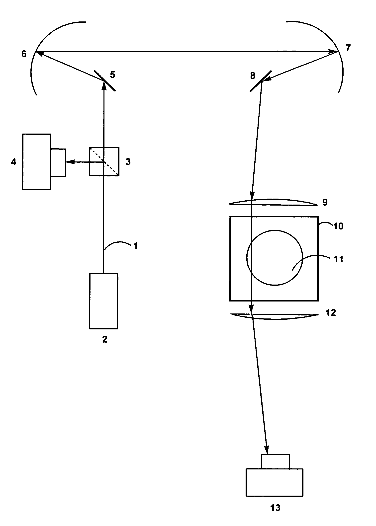
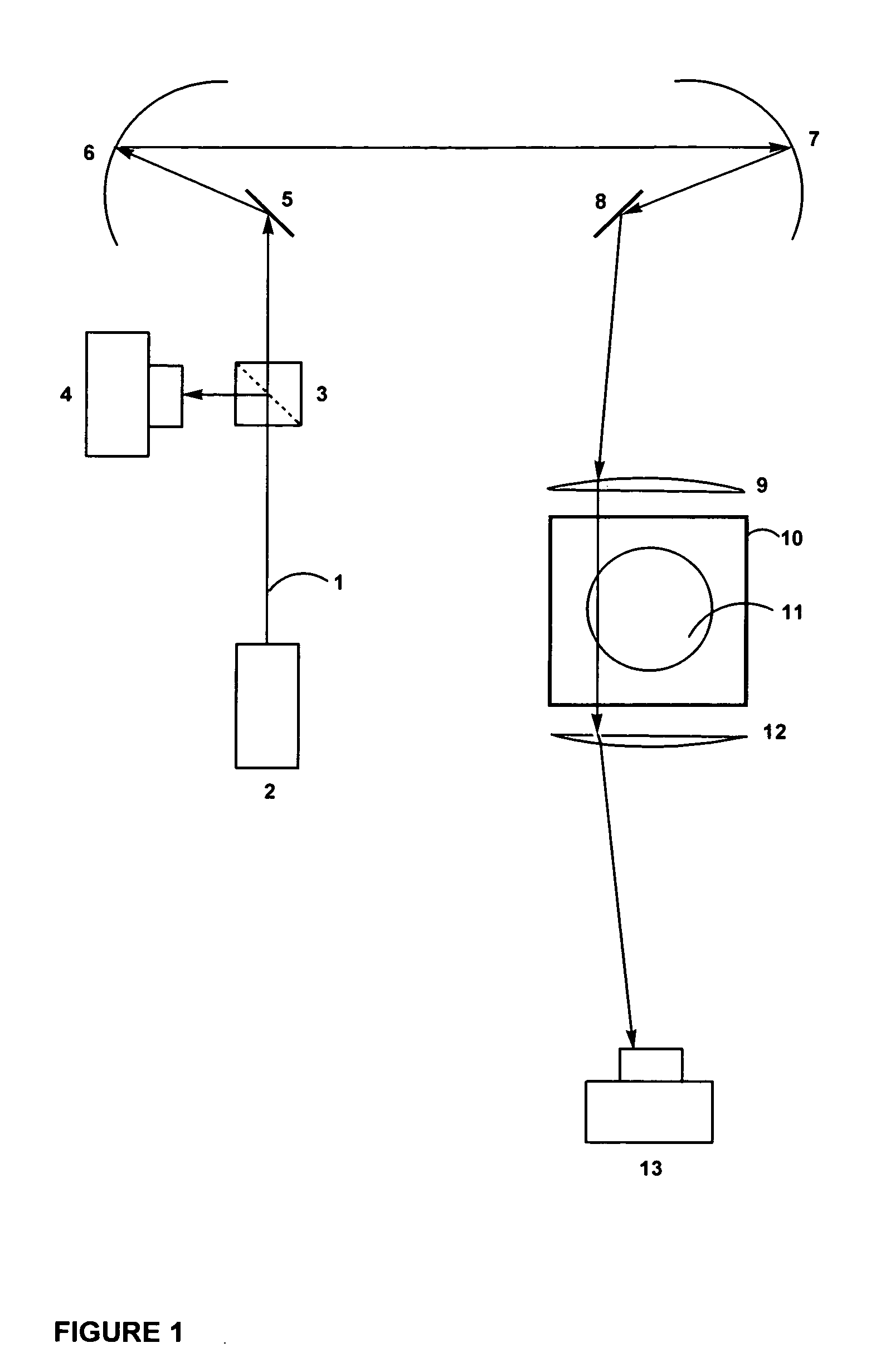
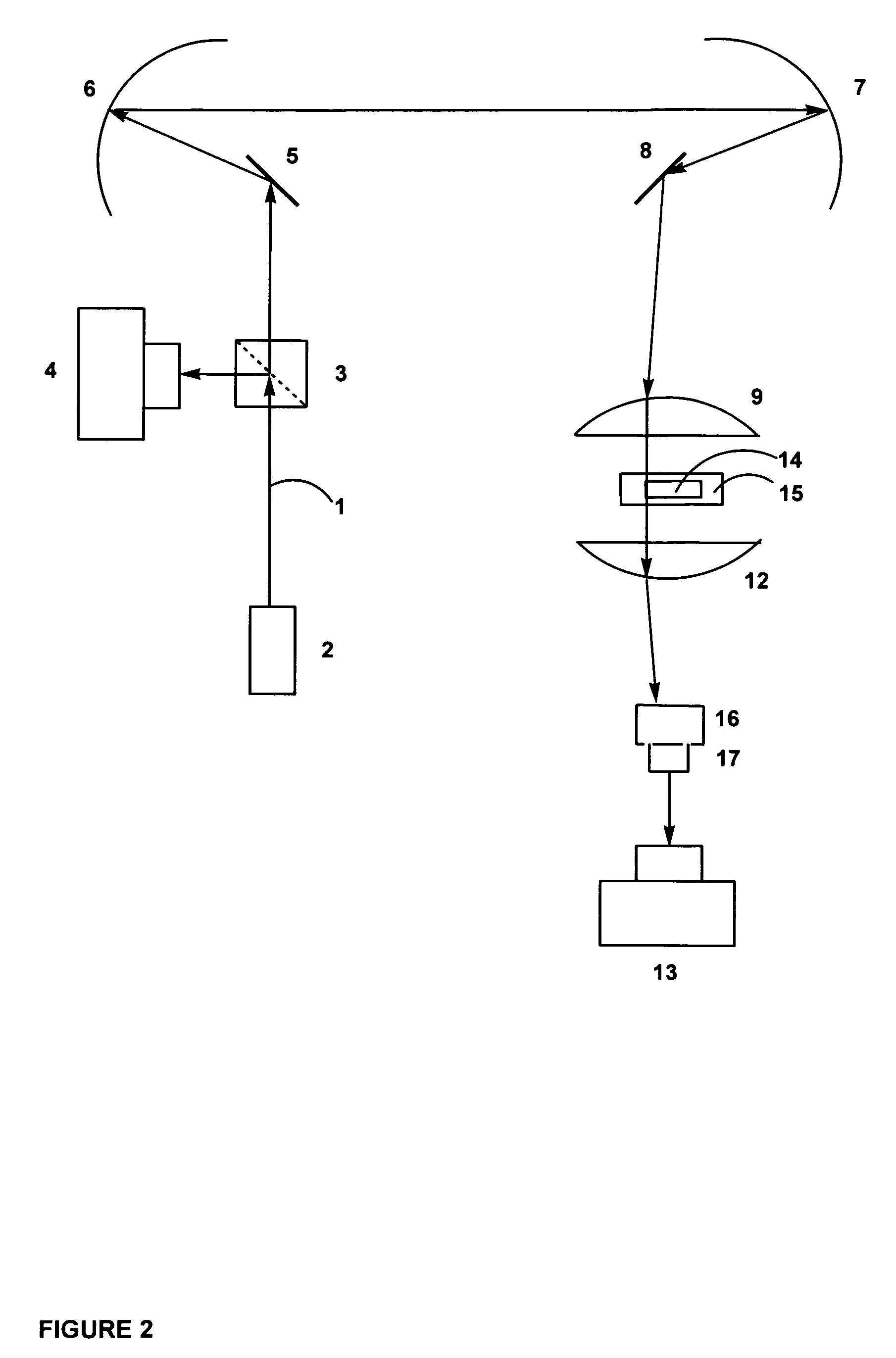
[0035]The invention provides for efficient and high-resolution imaging of three-dimensional light-transmitting objects through the use of high-quality optics and a combination of precision motion control and precise alignment of carefully selected optical elements. According to the invention, galvanometer controlled rotating plane mirrors and stationary converging lenses, either with or without relay optics (consisting of, for example, a pair of paraboloidal or spherical mirrors), or using a commercially available laser “scan head”, provide a means to scan an object along two axes. The net result of the optical arrangement is that a laser- or collimated light beam executes a two-dimensional scan across the sample in directions perpendicular to its direction of propagation. One embodiment provides a Cartesian raster scan suitable for three-dimensional image reconstruction using parallel-beam back-projection techniques. Alternative embodiments include, but are not limited to, devices ...


PUM


Abstract

Disclosed are scanning devices which measure and quantify optical properties within an object such as the absorption of light, refractive index, light scattering, fluorescence, and phosphorescence. Through the use of two rotating plane mirrors and two paraboloid mirrors, a laser light beam is made to traverse the object to be scanned wherein the beam is always parallel to the optical axis. The invention provides an improvement over previously reported scanning devices by virtue of increased speed and resolution. Two-dimensional projections gleaned by each scan of the object are reconstructed into a three-dimensional image through the use of various computer techniques.

Description

CROSS-REFERENCES TO RELATED APPLICATIONS[0001]This application claims the benefit of U.S. Provisional Application Ser. No. 60 / 925,178, filed Apr. 19, 2007.STATEMENT REGARDING FEDERALLY SPONSORED RESEARCH OR DEVELOPMENT[0002]Not Applicable.REFERENCE TO A SEQUENCE LISTING[0003]Not Applicable.FIELD OF THE INVENTION[0004]The invention relates to an optical scanning apparatus which measures the three-dimensional distribution of optical properties within the volume of an object.BACKGROUND OF THE INVENTION[0005]The invention provides a device which makes non-invasive, quantitative, and precise measurements of optical properties across the three-dimensional volume of objects which transmit light. The invention is within the general field of optical computed tomography (optical CT). The invention is directed to devices which measure and quantify optical properties which include, but are not limited to, absorption of visible light, absorption of ultraviolet light, absorption of infrared light...

Claims


Application Information

Patent Timeline
Patent Type & Authority Applications(United States)
IPC IPC(8): G02B6/06
CPCG01N21/4795
Inventor DORAN, SIMON JOHNKRSTAJIC, NIKOLA
Owner DORAN SIMON JOHN
Why Eureka
Try Eureka