Actuator Having An Electric Actuating Motor And Controllable Friction Clutch Having Such An Actuator

a technology of electric actuating motor and actuator, which is applied in the direction of electrical apparatus, dynamo-electric machines, magnetic circuits, etc., can solve the problems of increasing the thermal load of the motor, affecting the efficiency, and requiring a larger, more powerful motor, so as to achieve small friction, reduce thermal load, and be sensitive

Inactive Publication Date: 2008-11-13
MAGNA STEYR FAHRZEUGTECHN
View PDF3 Cites 13 Cited by
  • Summary
  • Abstract
  • Description
  • Claims
  • Application Information

AI Technical Summary

Benefits of technology

[0009]The measures according to the invention can be implemented in a variety of ways: in one first embodiment, the first zones having a low magnetic field strength and the second zones having a high magnetic field strength are produced by the permanent magnet(s) being magnetized variably over the circumference. This particularly simple and inexpensive design is particularly suitable for small actuating motors and mass production.
[0012]In order to maximize the reluctance braking according to the invention, at least some of the first zones having a low magnetic field strength cover approximately the same circumferential angle as the interspaces in the circumferential direction between the pole teeth, and this circumferential angle is in the range between 0.2 and 0.3 times the circumferential angle of the pole teeth. As a result, the lines of force of the magnetic field covered by the permanent magnets come to lie such that their braking effect is particularly great.
[0014]One particularly simple design which at least differs from the conventional design consists in the fact that the first part is the stator, and the second part is the inner rotor. One particularly advantageous and maintenance-free design is possible when the motor is driven electronically. With such a driving method, the commutation can be implemented electronically. In this design, the second part is the stator, and the first part is the inner rotor. This is possible without extra complexity in terms of hardware if an electronic driving system is provided in any case.
[0016]In one particularly advantageous embodiment of such a clutch, the transmission mechanism is a toothed gear, and the actuating element comprises two ramp rings which can be rotated in relation to one another, it being possible for at least one to be rotated depending on the arrangement. Such an actuating element is subject to particularly little friction and is particularly sensitive, and the actuator can react very rapidly and with little inertia thanks to the design according to the invention.

Problems solved by technology

However, this considerably impairs the efficiency and requires a larger, more powerful motor.
Although the current is lower, it does result in an increased thermal load on the motor over a relatively long period of time and requires energy.
Thirdly: an additional brake, which considerably increases the design complexity and needs to be driven separately.
All three possibilities are unsatisfactory, irrespective of the type or design of actuating motor.

Method used


Image

  • Actuator Having An Electric Actuating Motor And Controllable Friction Clutch Having Such An Actuator
  • Actuator Having An Electric Actuating Motor And Controllable Friction Clutch Having Such An Actuator
  • Actuator Having An Electric Actuating Motor And Controllable Friction Clutch Having Such An Actuator

Examples


Embodiment Construction

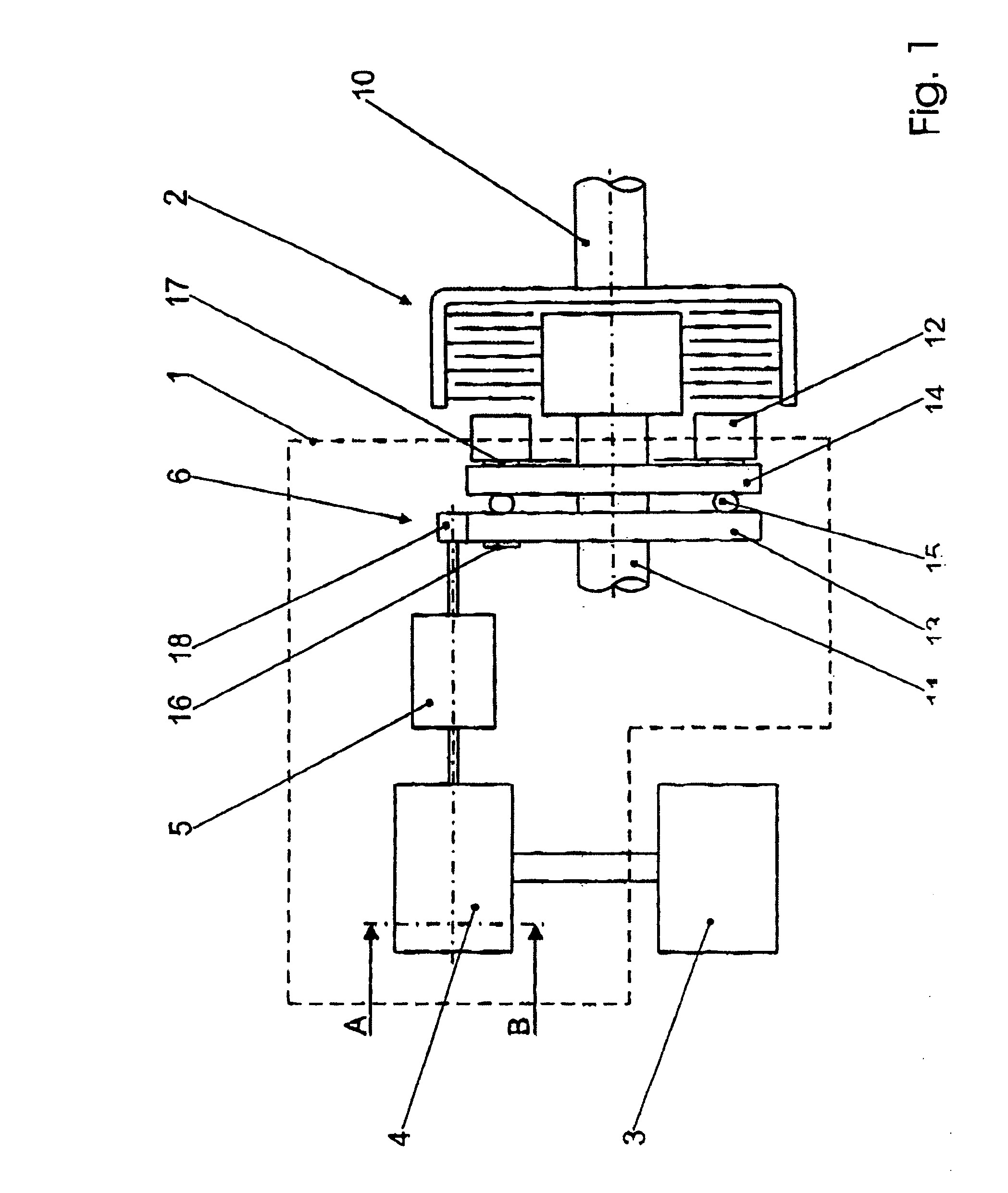
[0023]In FIG. 1, the actuator is denoted by way of summary by 1 and the clutch by 2. The actuator comprises an actuating motor 4, which is driven by a control device 3, a transmission mechanism 5 and an actuating element 6, by means of which a specific contact-pressure force or a specific torque to be transmitted is set at the clutch 2. The torque to be transmitted by the clutch 2 is determined by the control device 3 from variables relating to the dynamics of vehicle movement or other variables and is set correspondingly via the current supply to the actuating motor 4.

[0024]The clutch 2 itself, a multiple-disk clutch, is only illustrated schematically, as it is of conventional design. It comprises a primary part 10 having a primary shaft and primary disks and a secondary part 11 having a secondary part and secondary disks. The disks of the two parts 10, 11 can be pressed together by means of a contact-pressure plate 12, which is acted upon by an actuating element 6. The actuating e...


PUM


Abstract

An actuator comprises an electric actuating motor, a transmission mechanism and an actuating element, the actuating motor being a DC motor which comprises a first part having permanent magnets and a second part having windings and pole teeth. In order to be able to hold the actuator in any desired, adopted position without any additional apparatuses, the first part (30) has alternately first zones having a low magnetic field strength (31) and second zones having a high field strength (32) over its circumference, the circumferential angle (33) of the second zones (32) being equal to the circumferential angle (38) of the pole teeth (37) of the second part (35), the number of pole teeth (37) being selected such that all of the second zones (32) are always passed at the same time by a pole tooth (37), with the result that, in the event of a rotation in the state in which there is no current flowing, a pulsating torque is exerted between the first part (30) and the second part (35).

Description

BACKGROUND OF THE INVENTION[0001]The invention relates to an actuator comprising an electric actuating motor, a transmission mechanism and an actuating element, it being possible for the actuating element to be brought into a specific position by the actuating motor being driven and also to be held in this position, and the actuating motor being a DC motor which comprises a first part with a number of permanent magnets distributed over the circumference and a second part which has pole teeth having windings, which are fed with commutated current, and it being possible for one of the two parts to be rotated in relation to the other.[0002]Actuators are used for automation purposes in a wide variety of systems and apparatuses, in particular also for operating gear mechanisms, for actuating controllable clutches, for example in motor vehicles, and also for window winders, seat adjustment devices or the like in motor vehicles. In all of these applications it is necessary to hold the swit...

Claims


Application Information

Patent Timeline
Patent Type & Authority Applications(United States)
IPC IPC(8): H02K1/00H02K7/108F16D23/12F16D27/00H02K7/10H02K7/106H02K7/116H02K21/16H02K23/04H02K29/03
CPCF16D27/004H02K7/10H02K7/106H02K7/108H02K7/116H02K21/16H02K23/04H02K29/03
Inventor REISINGER, KARL
Owner MAGNA STEYR FAHRZEUGTECHN
Why Eureka
Try Eureka