Bounce drive actuator and micromotor

a micro-rotor and actuator technology, applied in the field of photolithographically patterned bda micro-rotors, can solve the problems that conventional sda-based micro-motors or micro-fan devices have limited commercial applications, and achieve the effects of reducing drive power, prolonging life, and prolonging li

Inactive Publication Date: 2008-11-13
SUNONWEALTH ELECTRIC MACHINE IND
View PDF16 Cites 12 Cited by
  • Summary
  • Abstract
  • Description
  • Claims
  • Application Information

AI Technical Summary

Benefits of technology

[0009]Compared with the conventional SDA devices, present invention provides a shorter and wider bushing structure in the BDA-plate design to increase the flexural rigidity of plate and to reduce the contact (friction) area of the bending plate and the insulator substrate under the same applied voltage as the priming value of SDA-plate. Any additional electrostatic load beyond the priming voltage can not deflect the free end of BDA-plate anymore and results in the bushing compressed and introverted. When the applied voltage was removed, the stored strain energy will bounce the actuator backward since the friction force of bushing is larger than the free end of BDA-plate.
[0010]Furthermore, a novel rib and flange structure design for the improvement of lifetime (>100 hrs) and rotational speed (>30 rpm) of BDA micro motor was also demonstrated in this invention.

Problems solved by technology

The conventional SDA-based micro motor or micro fan devices have limited commercial applications due to its shorter lifetime, high driving power and sudden reverse rotation.

Method used


Image

  • Bounce drive actuator and micromotor
  • Bounce drive actuator and micromotor
  • Bounce drive actuator and micromotor

Examples


Embodiment Construction

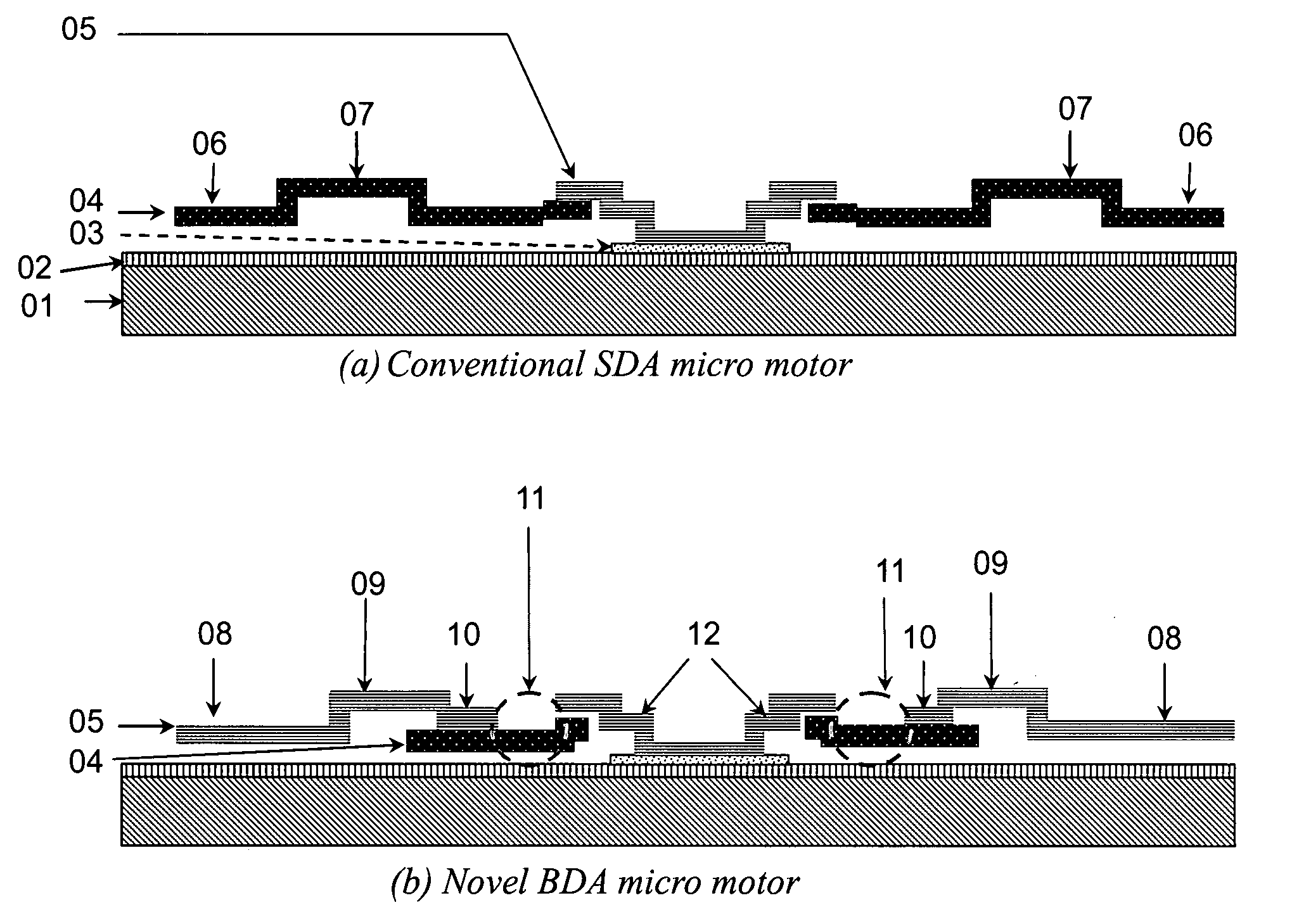
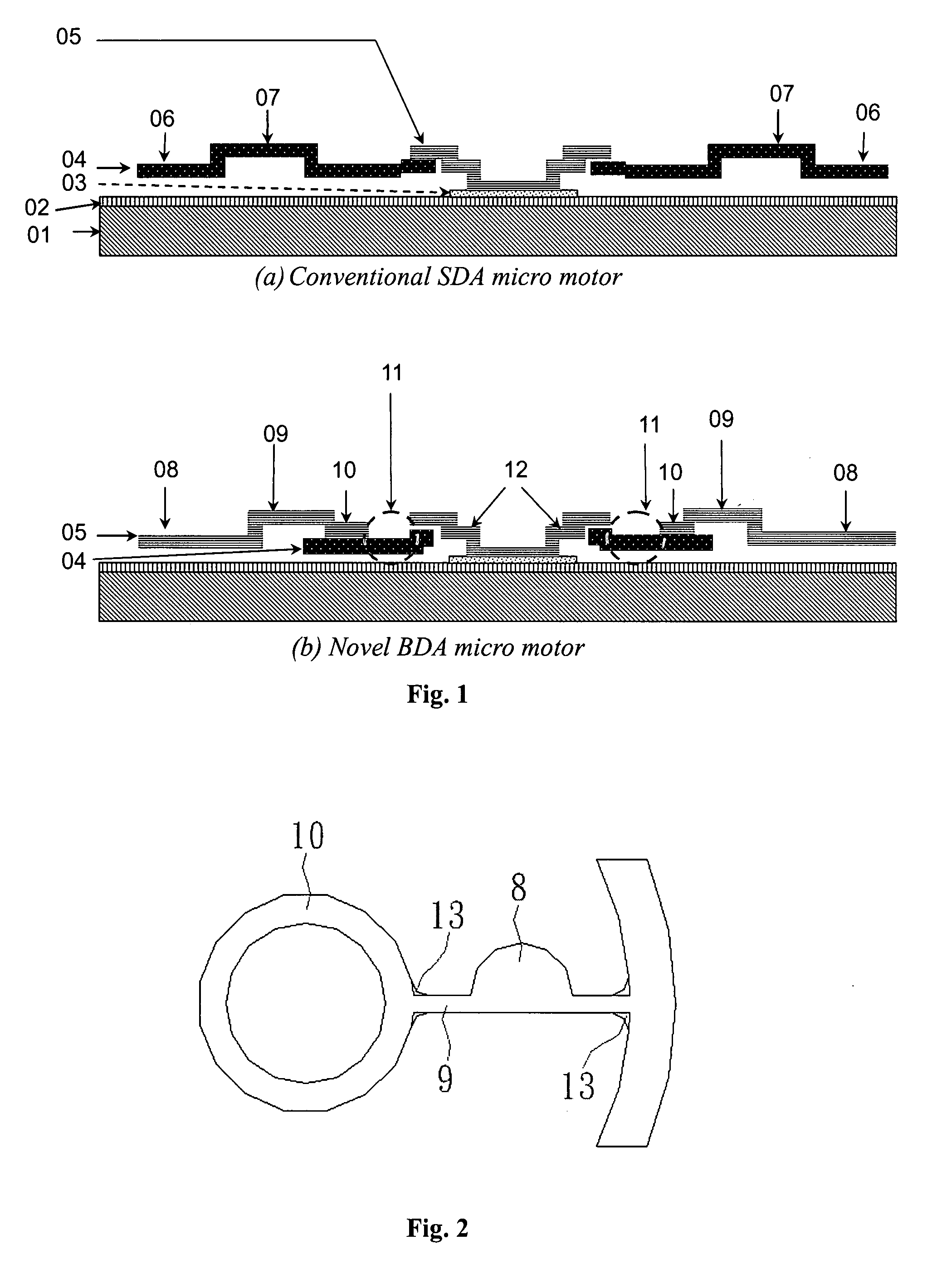
[0074]Conventional SDA micro motor has limited commercial applications due to its short lifetime, high driving power and sudden reverse rotation. FIG. 1 shows the main structures of conventional SDA micro motor and novel BDA micro motor from the simulated result of the L-Edit software. To enhance the break resistance (results from twist force) of the supporting beam (09), present invention utilizes the polysilicon-3 (05) layer to simultaneously construct the BDA-plate (08), supporting beam (09), ring (10) and the cover (12), which form a thicker “rib” structure (11) (stacked by Poly Si-2 (04) and Poly Si-3 (05) layers) adjacent to the ring (10) part; thus, the flexural rigidity and the lifetime of BDA micro motor can be improved.

[0075]FIG. 2 shows a novel “flange (13)” layout proposed in present invention. The flange design can further enhance the structure robustness of the supporting beam to further improve the yield of the BDA micro motor and reduce the crack failure under actuat...


PUM

PropertyMeasurementUnit
lengthaaaaaaaaaa
aspect ratioaaaaaaaaaa
lengthaaaaaaaaaa

Abstract

Provided is the design and fabrication of the novel bounce drive actuator (BDA) for the development of a new-type micro rotary motor. Although the scratch drive actuator (SDA) micro motor has been developed more than one decade, such device has limited commercial applications due to its shorter lifetime, high power consumption and sudden reverse rotation. In contrast, present invention proposes an innovative BDA micro rotary motor with different actuating mechanism and improved performance. Several significant investigations shown in this research present that the length of the SDA-plate is longer than 75 μm and the plate length of the BDA is less than 75 μm. Under the same driving power and frequency with SDA-based micro motor, the BDA-based micro rotary motor exhibited a consistent “reverse” rotation and a higher speed. BDA has higher flexural rigidity due to its shorter length of plate; thus, the contact area of the bending BDA-plate and the insulator substrate will substantially be reduced even under the same applied voltage as the priming value of SDA-plate. Furthermore, a novel rib and flange structure design for the improvement of lifetime (>100 hrs) and rotational speed (>30 rpm) of BDA micro motor was also demonstrated in this invention.

Description

FIELD OF THE INVENTION[0001]This invention generally relates to photolithographically patterned BDA micro rotary motor for micro-electromechanical systems (MEMS) applications. This invention also relates to a new BDA actuating mechanism and performance improvements of the conventional electrostatic drive micro rotary motor. The major technology adopted in present invention is the polysilicon-based surface micromachining process of MEMS technology, with the advantages of batch fabrication, low cost and high compatibility with integrated circuit technology.BACKGROUND OF THE INVENTION[0002]The development and application of miniaturization technology is the major trend of modem science. In particular, integrated circuits (IC) and microelectromechanical systems (MEMS) technologies are the rudimentary methods of the microscopic world in the recent years.[0003]Appendix 1 shows a conventional scratch drive actuator (SDA) with precise and stepwise linear motion mechanism.[0004]According to ...

Claims


Application Information

Patent Timeline
Patent Type & Authority Applications(United States)
IPC IPC(8): G03F7/20
CPCH02N1/004B81B3/0021B81C1/0019
Inventor HORNG, ALEXHUANG, I-YUCHEN, GUAN-MING
Owner SUNONWEALTH ELECTRIC MACHINE IND
Why Eureka
Try Eureka