
Systems and Methods For Testing using Microfluidic Chips

a technology of microfluidic chips and microfluidic chips, which is applied in the field of systems and methods for testing using microfluidic chips, can solve the problems of catastrophic delay, inability to communicate the results of testing, and inability to meet the needs of laboratory glassware, so as to reduce processing time and materials, prevent cross-contamination, and improve control

Inactive Publication Date: 2008-11-13
THE TRUSTEES OF THE UNIV OF PENNSYLVANIA
View PDF22 Cites 288 Cited by
  • Summary
  • Abstract
  • Description
  • Claims
  • Application Information

AI Technical Summary

Benefits of technology

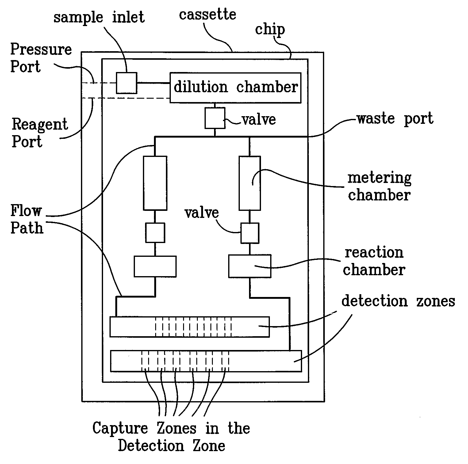
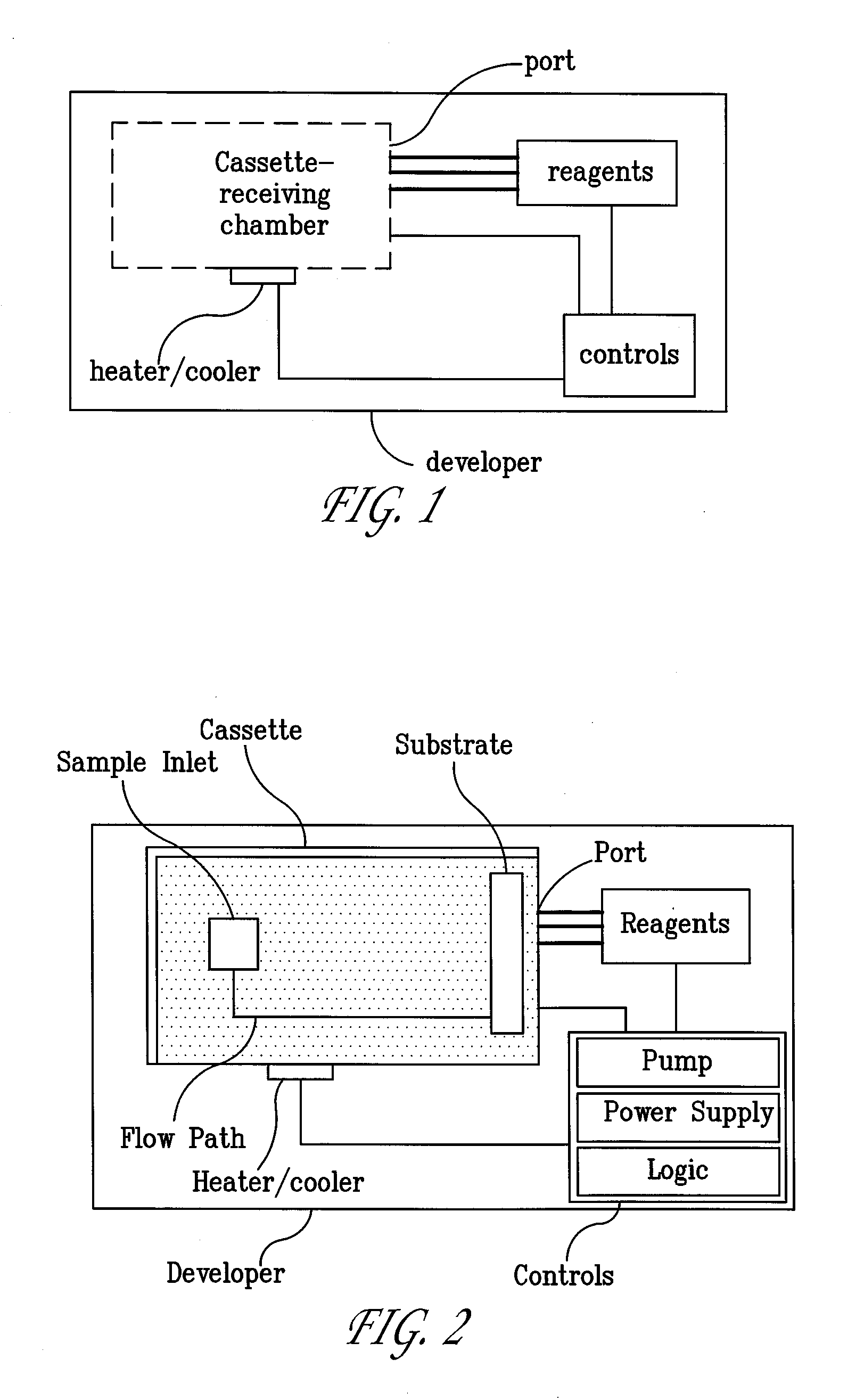
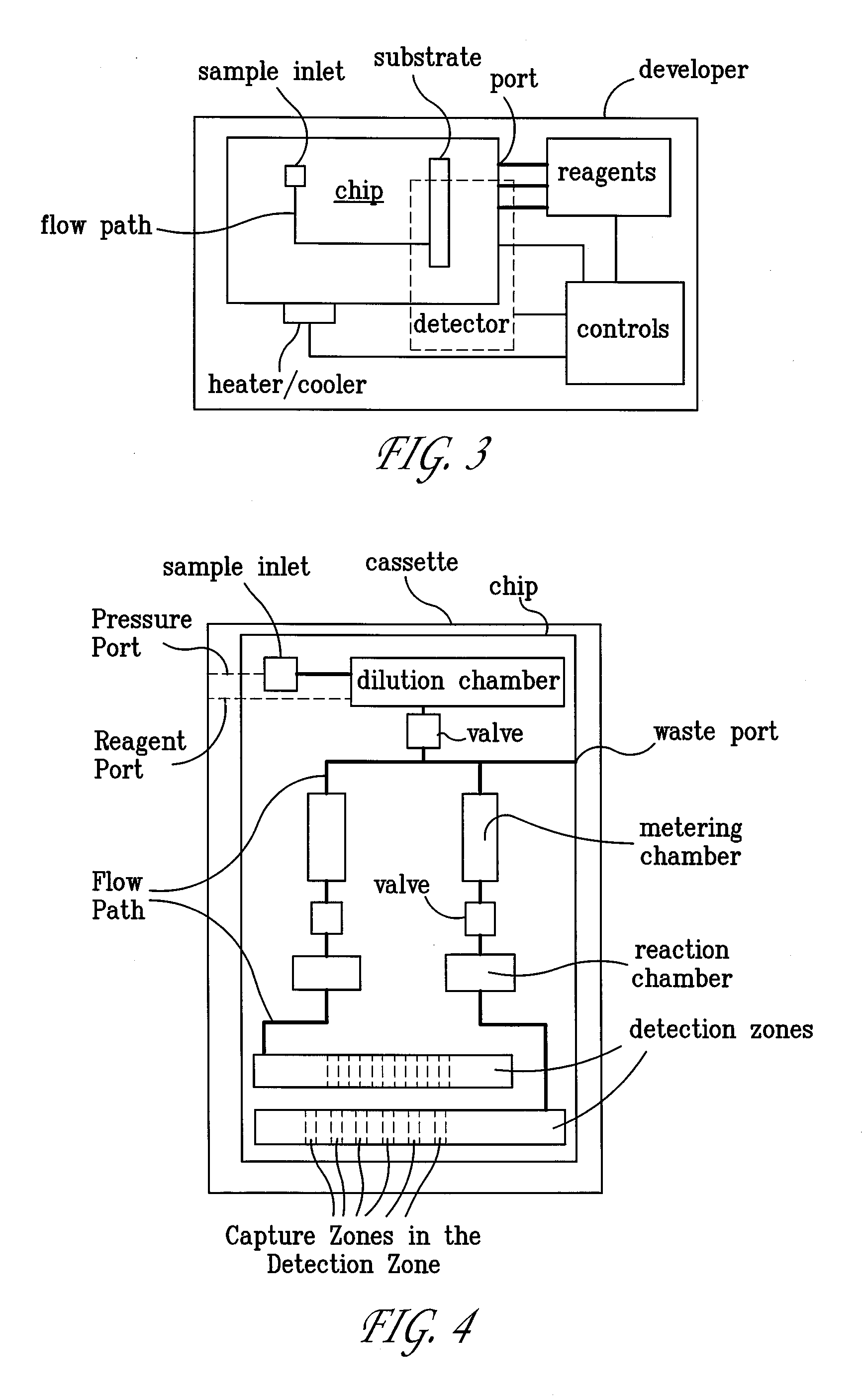
[0005]The present invention relates to sample processing using a microfluidic chip. Microfluidic refers to the fact that a fluid is propelled through a system, allowing greater control. In some embodiments, the chips reduce processing time and materials. In some embodiments, the chips accommodate samples without pretreatment, or in a self-contained state to prevent cross-contamination. In some embodiments, the system allows for automatic processing. The present inventions also are suitable for use analyzing samples at the point of care, and in clinical laboratories, if the above-described delay is not a factor.
[0020]The present invention also provides cassettes that reduce processing time and materials. In some embodiments, the cassettes accommodate samples without pretreatment, or in a self-contained state to prevent cross-contamination. In some embodiments, the system allows for automatic processing. The present inventions also are suitable for analyzing samples at the point of care, and in clinical laboratories, if the above-described delay is not a factor.

Problems solved by technology

While clinical laboratories excel at detecting proteins and nucleotides, including genetic information, disease-causing agents, and indicators of disease or disorders, there is always a delay between sample collection and communication of the results of testing.
In certain circumstances, such as a highly infectious outbreak or incident of bioterrorism, such a delay could be catastrophic.
This presents an unacceptable lag.
Testing by clinical laboratories does not remedy the lag, because of the above-mentioned delay between acquiring a sample and informing the individual of the test results.

Method used


Image

  • Systems and Methods For Testing using Microfluidic Chips
  • Systems and Methods For Testing using Microfluidic Chips
  • Systems and Methods For Testing using Microfluidic Chips

Examples


Embodiment Construction

[0061]The present invention may be understood more readily by reference to the following detailed description taken in connection with the accompanying figures and examples, which form a part of this disclosure. It is to be understood that this invention is not limited to the specific devices, methods, applications, conditions or parameters described and / or shown herein, and that the terminology used herein is for the purpose of describing particular embodiments by way of example only and is not intended to be limiting of the claimed invention. Also, as used in the specification including the appended claims, the singular forms “a,”“an,” and “the” include the plural, and reference to a particular numerical value includes at least that particular value, unless the context clearly dictates otherwise. The term “plurality”, as used herein, means more than one. When a range of values is expressed, another embodiment includes from the one particular value and / or to the other particular va...


PUM

PropertyMeasurementUnit
Lengthaaaaaaaaaa
Lengthaaaaaaaaaa
Temperatureaaaaaaaaaa

Abstract

Disclosed are methods, devices and systems for biological and chemical sample processing using microfluidic chips. The disclosed microfluidic chips contain at least two detection zones for interacting with pre-selected RNA sequences, DNA sequences, antibodies, or antigens to determine their presence in the sample. Systems are also described comprising a cassette having at least one port and a sample inlet in fluid communication with a detection zone for interacting with pre-selected RNA sequences, DNA sequences, antibodies, or antigens, or mixtures thereof, if present, in a sample. Methods for concurrent testing of at least two of RNA, DNA, antibody, and antigen in a sample are also described, as are methods for testing for pre-selected pathogens and microfluidic methods.

Description

CROSS-REFERENCE TO RELATED APPLICATIONS[0001]This application is a continuation-in-part of International Patent Application No. PCT / US2006 / 018481, filed May 11, 2006, which claims the benefit of priority to U.S. Provisional Application Ser. Nos. 60 / 679,797, filed May 11, 2005, 60 / 679,798, filed May 11, 2005, and 60 / 679,816, filed May 11, 2005, the disclosures of which are each incorporated herein by reference in their entireties. This application is also a continuation-in-part of International Patent Application No. PCT / US2006 / 018575, filed May 11, 2006, which claims the benefit of priority to U.S. Provisional Application Ser. Nos. 60 / 679,797, filed May 11, 2005, 60 / 679,798, filed May 11, 2005, and 60 / 679,816, filed May 11, 2005, the disclosures of which are each incorporated herein by reference in their entireties. This application is also a continuation-in-part of International Patent Application No. PCT / US2006 / 018534, filed May 11, 2006, which claims the benefit of priority to U....

Claims


Application Information

Patent Timeline
IPC IPC(8): C12Q1/70B01J19/00C12M1/40C12Q1/04C12Q1/68C12P19/34C12M1/34G01N30/00C12M1/33G01N33/536G01N33/00
CPCB01L3/502715Y10T436/143333B01L3/502738B01L3/565B01L7/52B01L7/525B01L9/527B01L2200/10B01L2200/141B01L2200/143B01L2300/022B01L2300/0864B01L2300/1822B01L2400/0415B01L2400/0487B01L2400/0605B01L2400/0633B01L2400/0672B01L2400/0677B01L2400/0688G01N35/00029G01N2035/00158B01L3/50273
Inventor CHEN, ZONGYUAN G.WANG, JINGMAUK, MICHAELBAU, HAIM H.MALAMUD, DANIELABRAMS, WILLIAMNIEDBALA, RAYMONDTANKE, HENDRIKUS JOHANNESCORSTJENS, PAUL L.A.M.
Owner THE TRUSTEES OF THE UNIV OF PENNSYLVANIA
Learn More