Continuously operating filtering apparatus

a filtering apparatus and continuous operation technology, applied in the field of continuous operation filtering apparatus, can solve the problems of reducing the cooking efficiency of the fryer, affecting the taste and appearance of food, and reducing the efficiency of the conventional filtering process, so as to prevent oil leakage

Active Publication Date: 2008-11-20
PITCO FRIALATOR LLC
View PDF15 Cites 40 Cited by
  • Summary
  • Abstract
  • Description
  • Claims
  • Application Information

AI Technical Summary

Benefits of technology

[0014]A sixth representative embodiment of the disclosure provides a method for urging oil flow through a deep fat fryer. The method includes the steps of providing a motor with a motor shaft projecting therefrom and providing an oil pump within a pump housing. The oil pump receives to

Problems solved by technology

The amount of foreign particulate matter within the oil increases as the fryer is used and hastens the degradation of the oil used in the frying process, degrades the taste and appearance of the food cooked within the fryer, and can reduce the cooking efficiency of the fryer.
This conventional filtering process is a relatively inefficient because the fryer cannot be operated while the oil is filtered because it must be drained from the vat and transferred to the filter apparatus.
Such systems require significant labor to maintain the filter in an acceptable operating state, often requiring the steps of cleaning the filter apparatus and replace the filter media.
This filtering schedule requires additional staff to be present at the establishment when not open for business, which increases the labor costs.
Also, filtering is often a relatively complicated process (or one with problematic or catastrophic results if performed improperly) such that only trained employees can effectively and safely perform this task.
Previous designs that have included continuous oil filtering structures have been disclosed in the prior art, and all include drawbacks that have limited their commercial success.
The filter receives only a portion of the oil flowing through the pump, which lengthens the time to filter the entire oil volume of the fryer.
In addition, the unfiltered oil passing through the heat exchanger can result in clogging of the heat exchange passages preventing proper flow.
Further, problems with the design of the disclosed pump associ

Method used


Image

  • Continuously operating filtering apparatus
  • Continuously operating filtering apparatus
  • Continuously operating filtering apparatus

Examples


Embodiment Construction

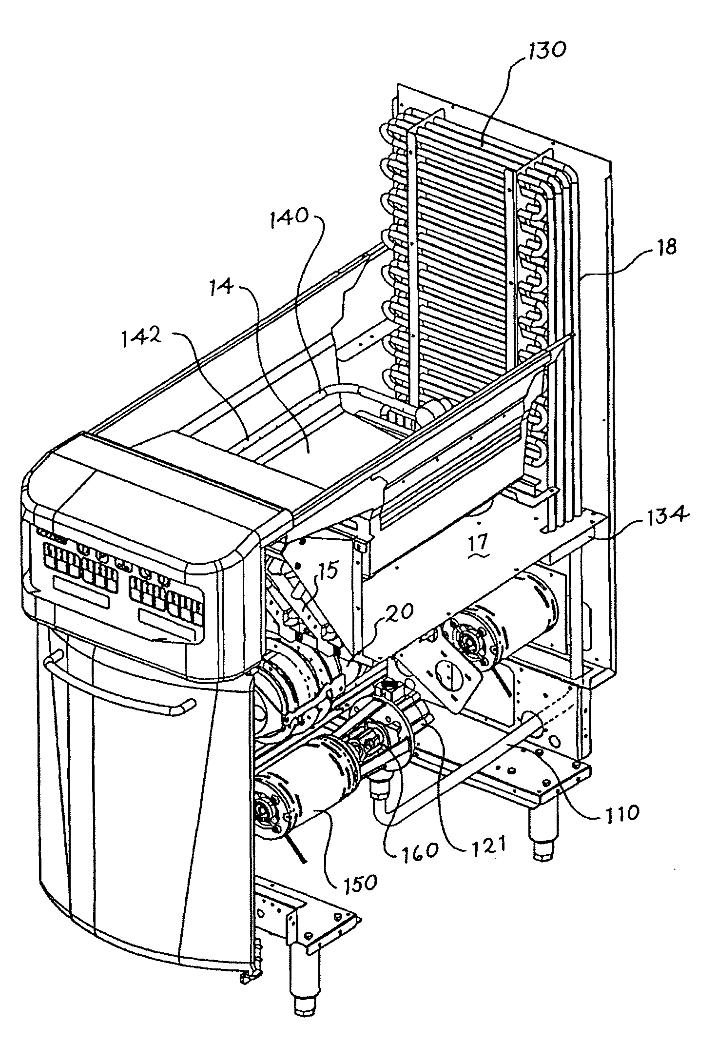
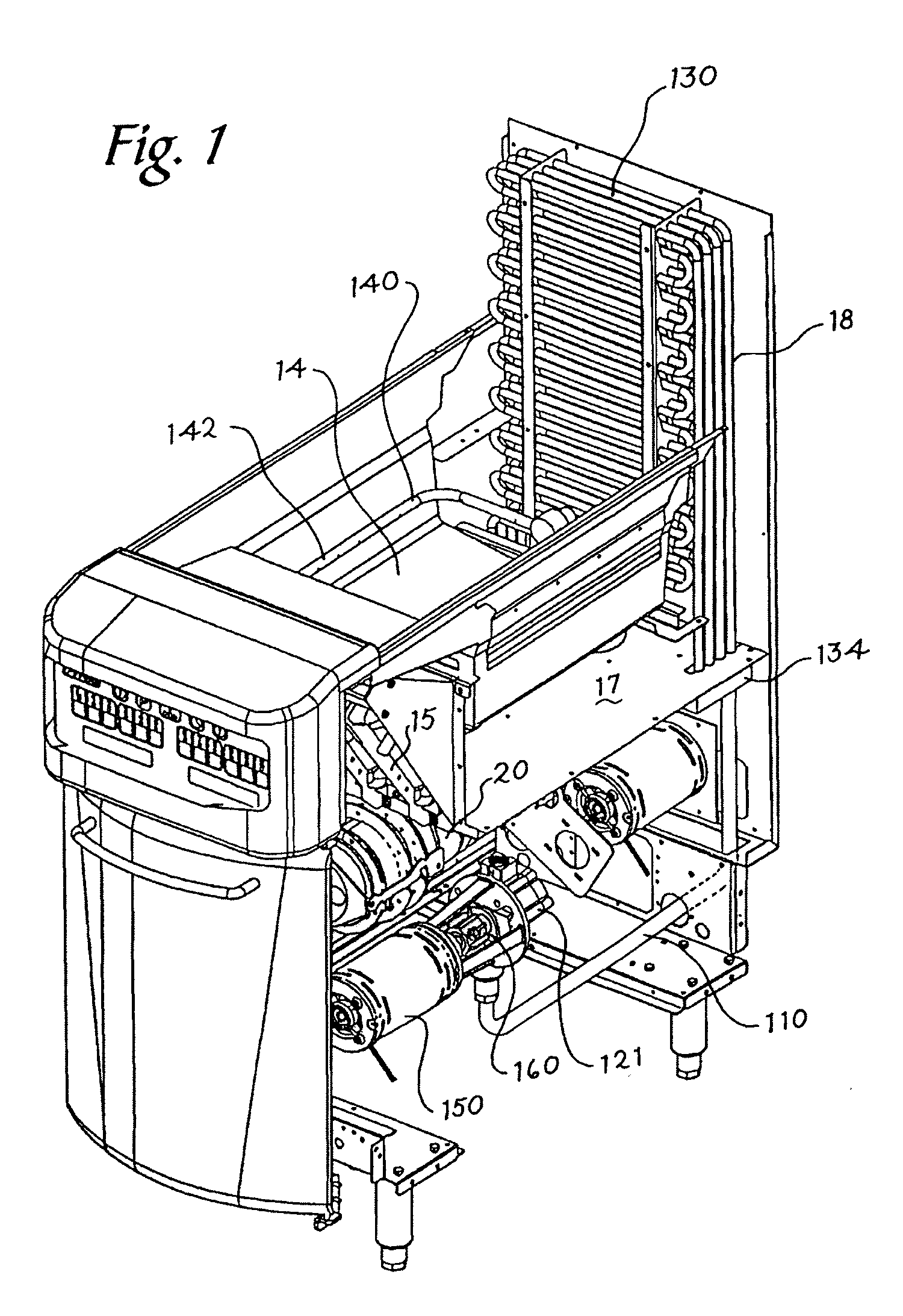
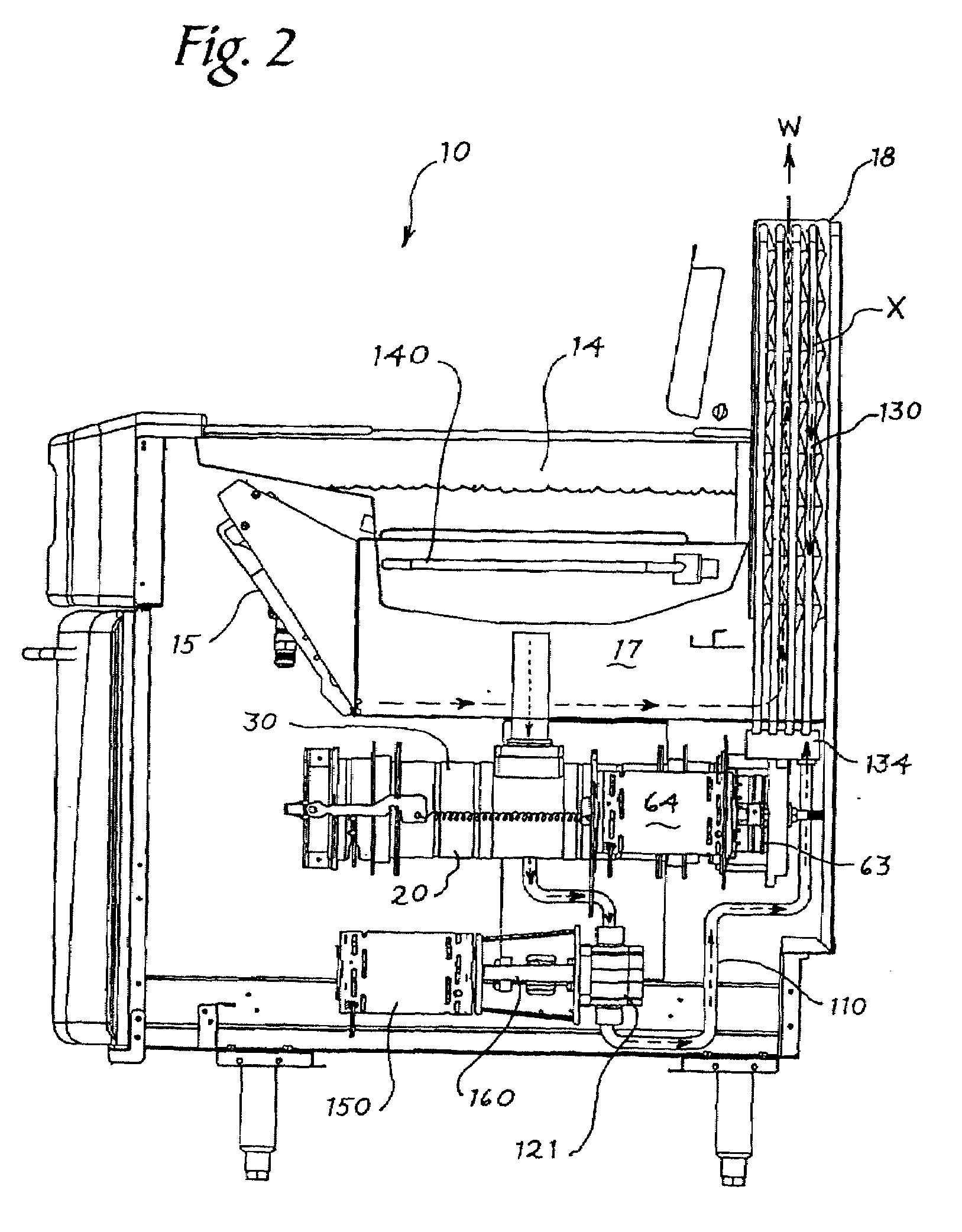
[0079]Turning now to FIGS. 1-2, a cooking appliance is provided. The cooking appliance may be a deep fat fryer 10, or another type of cooking appliance, such as a pasta cooker or rethermalizer, where a food product is cooked in a volume of heated liquid. One of ordinary skill in the art will recognize that the disclosure herein can be used successfully on other machines where there is a need to continuously remove particulate matter from a volume of liquid therein and / or provide heat to the liquid after removing particulate matter from the liquid.

[0080]The fryer 10 includes a housing 12 that mechanically supports all of the components of the fryer. The fryer 10 includes a vat 14 that provides a open volume for storing and heating a quantity of cooking oil for frying a food product placed therein. The fryer 10 further includes a heat source (not shown) that provides heat to the cooking oil stored within the open vat 14. The heat source may be a provided by burning natural gas or simi...


PUM


Abstract

A deep fat fryer with continuous oil filtering and purging of sediments therefrom during uninterrupted fryer operation is provided. The filter includes a cylindrical hollow housing with a first end and a second end and a hollow cylindrical screen with a longitudinal axis and first and second ends. The screen is disposed coaxially within the hollow housing to define an annulus therebetween. A piston mounted within the screen and reciprocatingly movable along the longitudinal axis between the first and second ends of the screen. A pump, seal, and associate motor are provided to provide continuous oil flow through the filter and the remainder of the fryer. A heat exchanger is provided downstream of the pump to transfer heat from the fryer to the oil flowing through the heat exchanger.

Description

CROSS REFERENCE TO RELATED APPLICATIONS[0001]This application claims priority under 35 U.S.C. §119(e) to U.S. Provisional Application No. 60 / 938,117, filed on May 15, 2007, to U.S. Provisional Application No. 60 / 972,972, filed on Sep. 17, 2007, and to U.S. Provisional Application No. 61 / 050,701, filed on May 6, 2008, the entirety of which are each fully incorporated by reference herein.TECHNICAL FIELD[0002]Deep fat fryers are known in the restaurant and food service industry as devices used to cook food products in a pool of heated oil. The heated oil is normally stored within a vat and the oil is heated from a heat source provided within the fryer. Fryers may include combustion heat sources that generate heat by burning natural gas or other types of fuel in the presence of a source of air, and direct the heated air to exchange heat with (either directly or indirectly) the oil within the vat. Fryers may also generate heat with electric heaters that generate significant amounts of he...

Claims


Application Information

Patent Timeline
IPC IPC(8): A47J37/12
CPCA47J37/1223Y10S210/08B30B9/067A47J37/1285B30B9/047A23L5/20A23V2002/00
Inventor SAVAGE, STEVEN J.PIERCE, CHARLES E.GARDNER, JOHN P.MCCABE, MARK E.LONGE, RORY A.JENSEN, KURT H.
Owner PITCO FRIALATOR LLC
Why Eureka
Try Eureka