Illuminating device, display device and optical film

a technology of illumination device and optical film, which is applied in the direction of discharge tube/lamp details, discharge tube luminescnet screens, discharge tubes/lamp details, etc., can solve the problems of low light efficiency, low brightness, and inability to enhance the effect of light use efficiency

Inactive Publication Date: 2008-11-20
DAWNCREST IP LLC
View PDF4 Cites 36 Cited by
  • Summary
  • Abstract
  • Description
  • Claims
  • Application Information

AI Technical Summary

Benefits of technology

[0010]In order to solve the above common problem, an object of the present invention is to easily realize a configuration in which only light having an unnecessary wavelength is cut and light having a necessary wavelength may be obtained efficiently.
[0011]In view of the above problems, an illuminating device according to the present invention includes: a light source that radiates light from a light-emitting portion; a filter layer that selectively reflects light in a particular wavelength region among light from the light source; and a phosphor that is excited with the light in the particular wavelength region, which is reflected by the filter layer, to emit light, in which the light reflected by the filter layer is converted by the phosphor so as to pass through the filter layer. Thus, a light component in a particular wavelength region may be decreased from light of a light-emitting portion, and a light component having other wavelengths may be increased. More specifically, by appropriately selecting a filter layer and a phosphor, the color tone (light-emitting wavelength characteristics) of an illuminating device may be controlled.

Problems solved by technology

Therefore, the use efficiency of light is low, and brightness is low.
Further, according to the configuration described in JP 2006-338901 A, all light having the wavelengths to be absorbed by the liquid crystal panel does not necessarily strike the phosphor to be color-converted, with the result that the use efficiency cannot be enhanced to a desired degree.
Therefore, it is not easy to eliminate only a green-based component and emphasize a red color more.
However, there are problems of power consumption, heat generation, and a cost, and hence, the above method is unrealistic.

Method used


Image

  • Illuminating device, display device and optical film
  • Illuminating device, display device and optical film
  • Illuminating device, display device and optical film

Examples


embodiment 1

[0039]FIG. 10 shows a configuration of a cross-section of a display device of this embodiment, and FIG. 11 schematically shows a configuration viewed from above. In this embodiment, as a light source 3, an LED package of a three-wavelength light-emitting type is used, which has a configuration in which a resin mixed with a green phosphor and a red phosphor is potted to a blue LED. Light from the light source 3 is brought to be incident upon a light guide body 4 from an incident plane thereof. The incident plane is formed so as to face the light source 3. The light guide body 4 has a configuration of guiding light incident from the incident plane and outputting the light from an output plane. For example, the light guide body 4 may be produced by injection-molding a transparent resin agent such as polycarbonate, acryl, ZEONOA, or ARTON. Further, the incident plane may be subjected to fine prism treatment so that light is scattered inside the light guide body 4 efficiently. Further, i...

embodiment 2

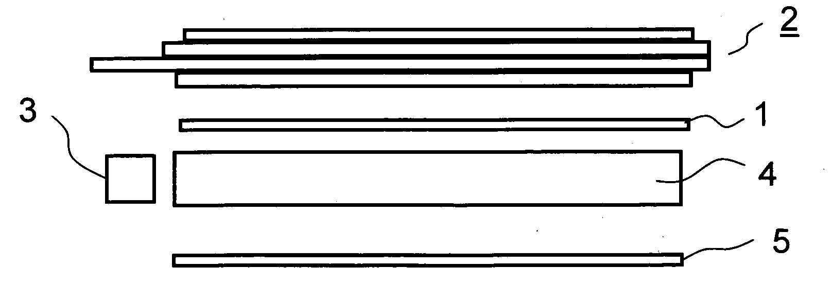
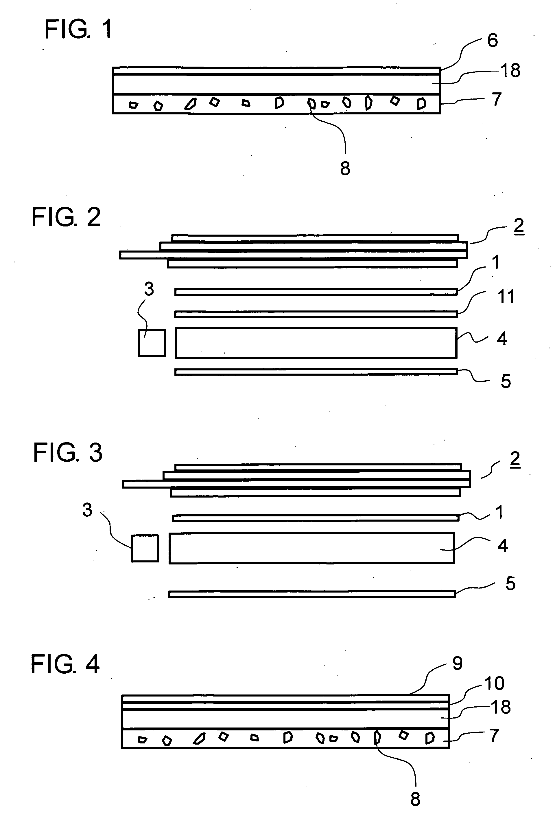
[0053]In this embodiment, a display device using a wavelength control film in which a filter layer and a phosphor layer are formed on a base film is described. FIG. 2 is a cross-sectional view schematically showing a configuration of a display device of this embodiment. The same description and application examples as those in Embodiment 1 are omitted if necessary. The light guide body 4 has a configuration of guiding light incident from an incident plane and outputting the light from an output plane. Light from the light source 3 is brought to be incident upon the light guide body from the incident plane of the light guide body 4. As the light source 3, an LED package of a three-wavelength light-emitting type is used, which has a configuration in which a resin mixed with a green phosphor and a red phosphor is potted to a blue LED. Further, the reflective plate 5 is placed on the reverse surface side of the light guide body 4. Light leaking outside from the reverse surface of the li...

embodiment 3

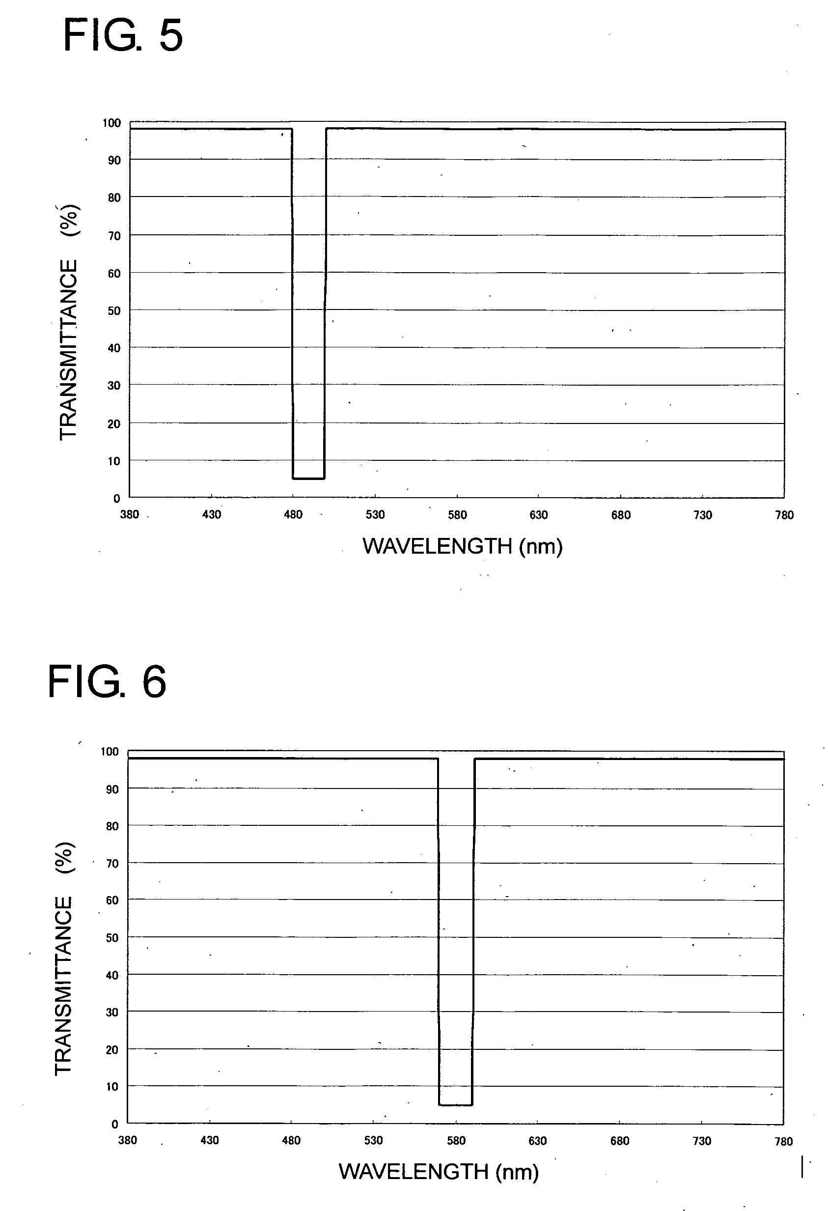
[0063]In this embodiment, the detail of the wavelength control film used in Embodiment 2 is described. FIG. 1 schematically shows a cross-sectional configuration of the wavelength control film of this embodiment. As shown in FIG. 1, the phosphor layer 7 containing the phosphor 8, and the filter layer 6 reflecting light having a particular wavelength are provided on the base film 18. The phosphor layer 7 has a configuration in which the phosphor 8 is dispersed in a transparent resin or the like. The phosphor 8 emits light having a wavelength different from an excitation wavelength, with the wavelength of light reflected by the filter layer 6 being the excitation wavelength. By using the wavelength control film with such a configuration, a light component having a particular wavelength (light reflected by the filter layer) may be decreased, and a light component having another particular wavelength (light emitted by the phosphor) may be increased. At this time, at least a part of a wa...


PUM


Abstract

To realize a configuration in which only light having an unnecessary wavelength is cut so that light having a necessary wavelength may be obtained efficiently, a filter layer that selectively reflects light having a particular wavelength and a phosphor layer containing a phosphor that is excited with the light having the particular wavelength to emit light are provided. Thus, the light reflected by the filter layer is converted into light having a different wavelength by the phosphor layer so as to pass through the filter layer. The filter layer is placed between a display element and a light source of an illuminating device, and the filter layer that selectively reflects a light component to be absorbed by the display element is used, whereby the light component to be absorbed by the display element is converted by the phosphor layer so as to pass through the display element. Accordingly, the illuminating device and a display device having very high luminance efficiency and color reproducibility may be realized.

Description

BACKGROUND OF THE INVENTION[0001]1. Field of the Invention[0002]The present invention relates to an illuminating device for illuminating display elements used in a portable information apparatus, a cellular phone, and the like, a display device having the illuminating device, and an optical film used in the illuminating device.[0003]2. Description of the Related Art[0004]In recent years, a liquid crystal display device, which obtains a high definition color image with small power consumption, is employed as a display device used in a cellular phone, a mobile computer, and the like. The liquid crystal display element requires an illuminating device because the liquid crystal display element is a non-selfluminescent display element that does not emit light. A superluminescent white LED is often used as a light source in the illuminating device.[0005]In particular, in a cellular phone, a reflection-type liquid crystal display device that has a large and bright opening or a double-side ...

Claims


Application Information

Patent Timeline
Patent Type & Authority Applications(United States)
IPC IPC(8): H01J1/62
CPCH01L33/44H01L33/507H05B33/145
Inventor KURIHARA, MAKOTOMORIHARA, TAKAFUMI
Owner DAWNCREST IP LLC
Why Eureka
Try Eureka