Multifilar cable catheter

a multi-filar cable and catheter technology, applied in the field of medical catheters, can solve the problems of length and unwieldiness, high cost and efficiency of construction, and the like, and achieve the effect of good pushability and trackability

Active Publication Date: 2008-11-20
COOK MEDICAL TECH LLC
View PDF54 Cites 42 Cited by
  • Summary
  • Abstract
  • Description
  • Claims
  • Application Information

AI Technical Summary

Benefits of technology

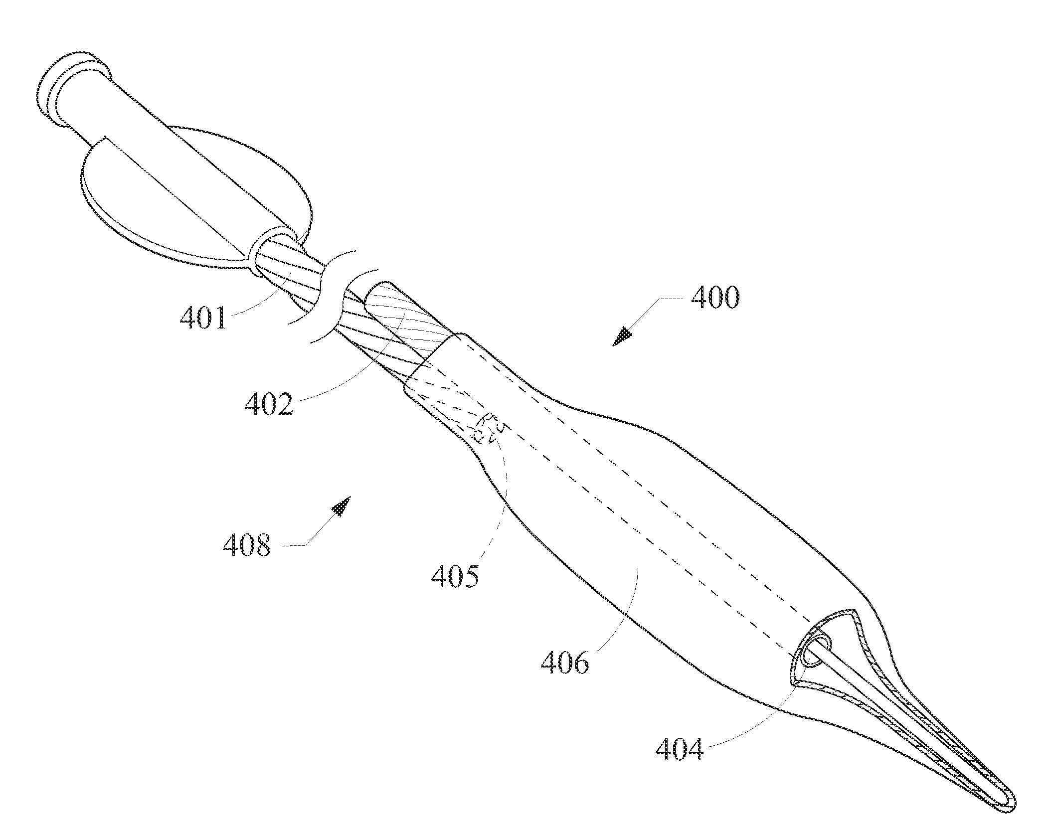
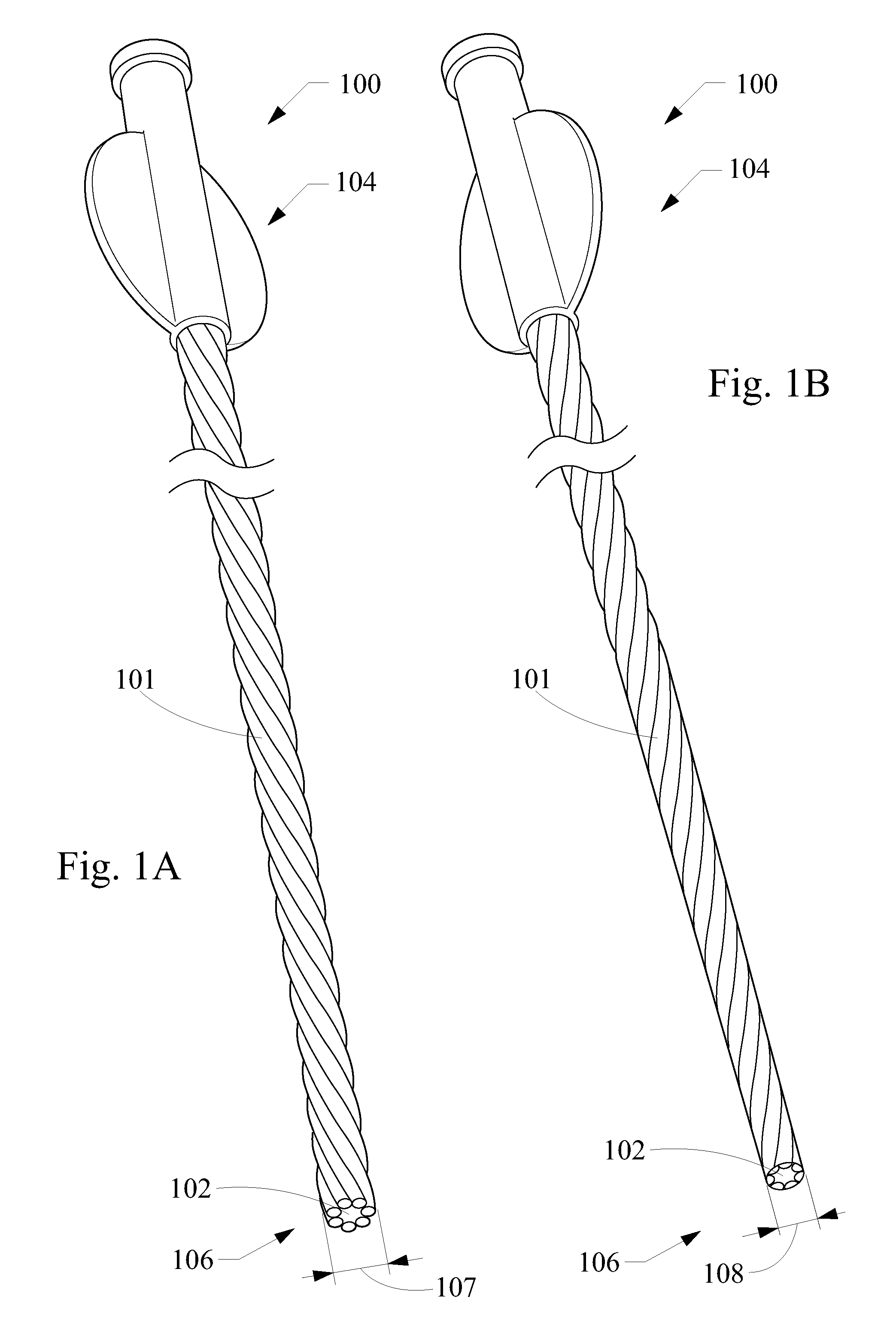
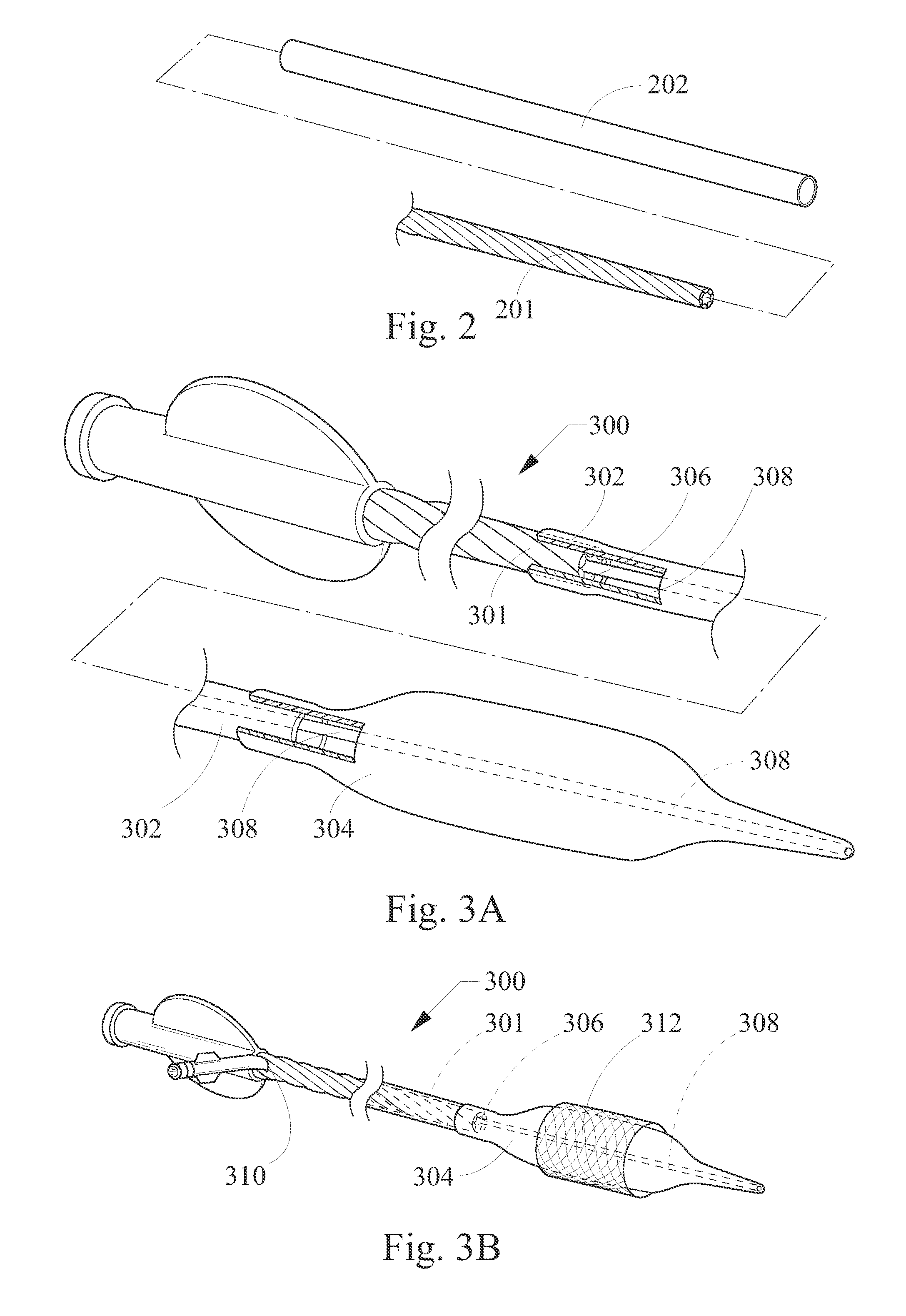
[0011]In one aspect the present invention provides a catheter device, adaptable for use in endovascular lumens or other body lumens, that has a construction of multifilar cable tubing for a substantial portion of its length and that is adaptable for use in a short-wire or long-wire configuration. The embodiments described and claimed herein provide a multifilar catheter shaft having good pushability and trackability. Embodiments of the present invention may be adaptable for a variety of applications (e.g., placement of expandable stents, balloon dilation of stenoses) and use in a variety of surgical locations (e.g., vascular, gastroenterological).

Problems solved by technology

A catheter having uniform properties throughout its length poses disadvantages in that it is likely to be too proximally flexible or too distally stiff.
This combination of materials poses problems of cost and efficiency in construction, and the junctions provide problematic possibilities for structural failure (such as binding, kinking, or even separation) as well as requiring specialized connection means.
Some long wire catheters rely almost wholly on placement of a wire guide therethrough to retain the needed stiffness, which presents the problems of length and unwieldiness discussed above.
Several different structures for shortened guide wire lumen dilation catheters have been proposed and used to obtain the desired physical properties described above, but each of these structures tends to suffer from several disadvantages.
For example, in a short wire catheter having a relatively flexible one-piece plastic design, because only a small portion of the wire guide extends through the catheter body near the distal end of the catheter shaft, the wire guide portion does not contribute to the pushability of the rest of the catheter shaft.
As a result, the proximal shaft portion of such a catheter has low column strength.
With such a configuration, the shafts and guide wire may tend to develop undesirable flexure (e.g., scissoring, bowing, buckling, kinking) when the balloon is being manipulated in a lumen.
This undesired flexure may cause an irregular exterior surface such as a sharp edge which can in turn cause injurious abrasions to the inner lining of the artery or other lumen (e.g. other body lumen or a working lumen of an endoscope).
This undesired flexure also leads to poor pushability and trackability of the catheter.
Having the first aperture at the aforementioned junction or in the second tubing creates a likelihood of undesired flexure (e.g., kinking or bunching) as there will be at least some portion of the more flexible second tubing unsupported by a wire guide, and therefore lacking column strength.
Not only may such undesired flexure injure an endovascular or other lumen housing the catheter, but it may close off an inflation lumen or other lumen of the catheter, which is undesirable.

Method used


Image

  • Multifilar cable catheter
  • Multifilar cable catheter
  • Multifilar cable catheter

Examples


example 1

[0067]An exemplary method of making a wire-guided balloon catheter 1200 is described with reference to FIGS. 12A-12K. Those of skill will appreciate that this and other embodiments may be constructed using alternative methods within the scope of the present invention. As shown in FIG. 12A, a multifilar tubular shaft 1202 is provided, including a monolayer tubular shaft of ten filars coiled together to form a shaft wall 1204 defining a shaft lumen 1206. The shaft 1202 includes a proximal end 1202a and a distal end 1202b, and it has desirable pushability and trackability characteristics, with a structure that tapers from a proximal outer diameter of about 0.05 inches to a distal diameter of about 0.04 inches. (NOTE: FIGS. 12A-12K, along with all other figures of the present application, may not be drawn to scale). Next, as shown in FIG. 12B, a PEBA barrier sleeve 1208 is placed around a distal region of the shaft wall 1204 and heated to sealingly shrink around it (1204).

[0068]Then, as...


PUM

PropertyMeasurementUnit
thicknessaaaaaaaaaa
pressuresaaaaaaaaaa
pressuresaaaaaaaaaa

Abstract

A balloon catheter device of the present invention includes an elongate catheter shaft comprising multifilar cable tubing having a proximal portion and a distal portion. The proximal portion includes a coating that allows the shaft to provide a patent fluid passage, and a part of the distal portion inside a balloon may be uncoated or otherwise open to the balloon lumen, allowing for passage of fluid through the shaft into the balloon lumen.

Description

TECHNICAL FIELD[0001]The present application relates to medical catheters, and more specifically to medical catheters useful in endovascular and other body lumens.BACKGROUND[0002]Medical delivery catheters are well known in the art of minimally invasive surgery for introduction of fluids and devices to sites inside a patient's body. For example, balloon dilation of luminal stenoses (e.g., in procedures such as angioplasty or balloon dilation of a bile duct), stent placement, and introduction of radio-opaque contrast fluids are common uses of catheters.[0003]The most widely used form of angioplasty makes use of a dilation catheter having an inflatable balloon at its distal end. In coronary procedures, a hollow guide catheter or wire guide typically is used for guiding the dilation catheter through the vascular system to a position near the stenosis (e.g., to a coronary arterial lumen occluded by plaque). Using fluoroscopy, the physician guides the dilation catheter the remaining dist...

Claims


Application Information

Patent Timeline
Patent Type & Authority Applications(United States)
IPC IPC(8): A61M31/00A61B6/00
CPCA61F2/95A61F2/958A61F2/966A61M25/0009A61M25/0023A61M25/005A61M2025/0183A61M25/0054A61M25/1002A61M25/104A61M2025/0046A61M2025/018A61M25/0052
Inventor LENTZ, DAVID CHRISTIAN
Owner COOK MEDICAL TECH LLC
Why Eureka
Try Eureka